MIT APP inventor Arduino Bluetooth Application Making Explained
MIT APP inventor Arduino Bluetooth Application- I have been using Bluetooth supported cell phone apps for monitoring and controlling different types of sensors and electrical loads. I designed all of my previous apps in Android Studio. A few months back I uploaded articles on how to design your own android app for controlling electrical loads and how to design your own android cell phone app for monitoring the sensors connected with the Arduino. These two articles got very popular and helped many boys and girls in designing their own cell phone apps for controlling and monitoring electronics connected with the Arduino. So, if you are into the Android Studio thing then you should read these articles. If you think programming is difficult for you and you are only comfortable with drag and drop type work then this article is for you. Because the Cell Phone App we are going to make today doesn’t require any coding. Amazing.
In this article, I am going to use the MIT APP Inventor for designing a Bluetooth supported App which can be used with Arduino boards with the help of a Bluetooth module like HC05 or HC06, or any other Bluetooth module. But, in this article, I will be using HC05 Bluetooth module which I have used in so many projects. You can also check my other Android based projects.
Without any further delay, let’s get started.
HC05 Bluetooth module:
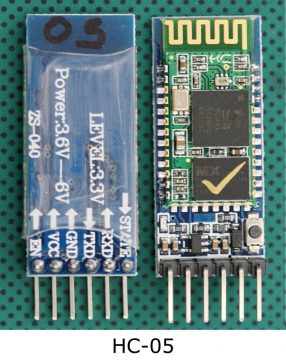
HC-05 module is an easy to use Bluetooth SPP (Serial Port Protocol) module, designed for transparent wireless serial connection setup.
Serial port Bluetooth module is fully qualified Bluetooth V2.0+EDR (Enhanced Data Rate) 3 Mbps Modulation with complete 2.4 GHz radio transceiver and baseband. It uses CSR Bluecore 04-External single chip Bluetooth system with CMOS technology and with AFH (Adaptive Frequency Hopping Feature). It has the footprint as small as 12.7mmx27mm. Hope it will simplify your overall design/development cycle.
As this is my first article on the MIT APP Inventor, so I will try to keep things simpler so that you guys can easily follow each and every step. So, instead of doing something complex, I will start with the LED, You know ? if you can control an LED it means you can control a transistor, a Mosfet, a relay etc. So, In this article we will going to learn how to control the LED connected with the Arduino Uno or Arduino Nano or Arduino Mega, using Bluetooth app. I will add two buttons which can be used to turn ON and turn OFF the LED connected with the Arduino board. In the future you can replace this LED with other electrical devices which you want to control. The cell phone app will wirelessly communicate with the Arduino with the help of the HC05 Bluetooth Module. So, what we have is at HC05 Bluetooth module? if you look at the front side it will look it will show you some kind of antenna here on hc-05 Bluetooth module and on the back side when we look at that we will see the every pin on this module. The first pin is enable en, second pin is VCC, the third pin is a ground and then the fourth one is a TXD and the fifth one is RXD. So this is how the pin label has been given on this hc-05 Bluetooth module.
Interfacing of HC-05 with Arduino:
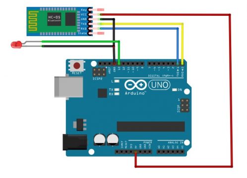
So let’s take this Bluetooth module and connect it to Arduino Uno. So here we have a Bluetooth module and you see on our Arduino Uno. The digital pin 0 is RXD and the digital pin 1 is TXD. In order to make communication between the HC-05 and Arduino we will connect TXD of the HC-05 to RXD of the Arduino and RXD of the HC-05 to TXD of the Arduino. The ground of the HC-05 should be connected to the ground of the Arduino. Connect the VCC of the HC-05 to the 5V of the Arduino.
This is how we will have to connect at HC-05 Bluetooth module with Arduino Uno then we will connect the led with the Arduino. The longer leg of the LED which is anode will going to connect to 13 pin of the Arduino and the shorter leg of the LED will going to connect to the ground. Don’t forget to add a current limiting resistor with one of the legs of the LED if incase you are using an LED below 5volts. You can select a 330 ohm resistor, which works perfect with 2.5v LEDS.
In order to make a successful communication, you will need to program the Arduino board. Next, we are going to write a very basic program to read the HC05 Bluetooth module and then control the LED as per the command received from the cell Phone App designed in MIT App Inventor.
Arduino Bluetooth Locking System with MIT App Inventor
Welcome to Sir Boateng Online! Today I will show you how to make an App using MIT App Inventor 2 and use it to control the Arduino Bluetooth locking system such as the Arduino based door lock system using HC 05 Bluetooth and Arduino Uno.
If you are unfamiliar with Arduino Uno, you can start from scratch with this previous tutorial, Arduino programming for beginners.
This project is far more secure than the traditional key-based system and electronic wireless lock system because it can generate a new password each time a user unlocks it, increasing your security level even further.
One disadvantage of using a key-based system is the possibility of your key being lost or stolen. Furthermore, an electronic wireless lock system that requires a password or passcode is not secure.
You are more likely to forget the password, and there is also a greater risk of a security breach by intruders.
Recommended Posts:
- Proteus Locking System with Keypad and Pincode
- Arduino Uno Programming for Beginners Part 1
- Top 8 Arduino Projects in Proteus with Source Code
- List of Final Year Engineering Projects for Students
- How To Fix TM1 Laptop Sound Drivers
Sir Boateng Online platform is always concerned with security. That is why we created this one-of-a-kind and more secure Do-it-yourself smart locking system, which will eliminate all security threats while also providing better and more robust locking options.
In fact, you’ll also learn how to create your own Android apps with MIT App Inventor 2.
These are the materials needed for this project.
List of Components
- Arduino UNO
- Bluetooth Hc05
- Light Emitting Diode (LED)
- Some Wires/Jumper Wires
- Servo Motor/ Magnetic locker
- 5V Battery/Power Bank
- USB Type B for Programming Arduino
We can begin the project (Bluetooth Locking System with Arduino and MIT App Inventor 2) once we have obtained all of the above components.)


