- Control LED Using MIT App Inventor and Arduino
- Digital Pins connection:
- Block diagram:
- About Bluetooth module HC-05:
- About serial communication:
- Step by step execution process:
- MIT App Inventor HC05 with Arduino Programming:
- MIT APP inventor Arduino Bluetooth Application Making Explained
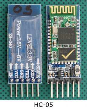
- HC05 Bluetooth module:
- Interfacing of HC-05 with Arduino:
Control LED Using MIT App Inventor and Arduino

Inventor of the MIT APP Arduino Bluetooth application. I have used Bluetooth mobile phone applications to monitor and control various types of sensors and electrical loads. I developed all my previous apps in Android Studio. A few months ago I uploaded articles on how to develop a custom Android app to control electrical loads and how to develop a custom Android mobile phone app to monitor sensors connected to Arduino. These two items have become very popular and have helped many boys and girls to develop their own mobile phone applications to control and monitor Arduino related electronics. So if you like Android Studio, you should read these articles. If you think that programming is difficult for you and you are comfortable working with just drag and drop, then this article is for you. Because the application for mobile phones that we are going to make today does not require programming. Marvellous.
In this article, I will use MIT APP Inventor to develop a Bluetooth enabled application that can be used with Arduino boards using a Bluetooth module such as the HC05 or HC06, or any other Bluetooth module. But in this article, I will use the HC05 Bluetooth module, which I have used in many projects. You can also check out my other Android projects.
Digital Pins connection:
| S.No | Digitalpin_connection |
| 1. | Digital pin 11 ( output) |
| 2. | Digital pin 12 ( output) |
| 3. | Digital pin 13 ( output) |
| 4. | Digital pin 0 ( Rx) |
| 5. | Digital pin 1 ( Tx) |
Block diagram:

About Bluetooth module HC-05:
HC-05 is a Bluetooth module which is designed for wireless communication. It uses serial communication to communicate with devices. HC-05 has a red LED which indicates connection status, whether the Bluetooth is connected or not. Before connecting to the HC-05 module this red LED blinks continuously in a periodic manner. When it gets connected to any other Bluetooth device, its blinking slows down to two seconds.
It is used for many applications like wireless headsets, game controllers, wireless mice, wireless keyboards and many more consumer applications. To communicate smartphone with the HC-05 Bluetooth module, the smartphone requires a Bluetooth terminal application for transmitting and receiving data.
About serial communication:
If the data is sent in series i.e. one after the other then the communication protocol is known as Serial Communication Protocol. In serial communication, data is sent in the form of bits i.e. binary pulses and it is well known that binary one represents the logic HIGH and zero represents the logic LOW.

Serial communication is the most widely used approach to transfer information between data processing peripherals. The protocol is a secure and reliable form of communication having a set of rules addressed by the source host (sender) and destination host (receiver) similar to parallel communication. there are several examples of Serial Communication Protocols such as CAN, ETHERNET, I2C, RS232, SPI, USB, 1-Wire, SATA etc.
Step by step execution process:
Creating Mobile APP using MIT APP inventor:
Step 1: Open the MIT app inventor website and click on “create apps”.
Step 2:I would like to give the name to the app as Bluetooth and then hit on OK so you see it creates a project with the name Bluetooth. It takes a couple of minutes and then it will straightaway take you to the project itself.

Step 3: Choose the option to start a new project, the window is shown below figure.

Step 4: In the designer section, start building the app interface.
Step 5: First select the “list picker” in the palette window and drag and drop it in the mobile window and modify the interface by changing the properties in the window.
Step 6: Now select “layout” in the palette and drop them in the mobile window and modify them using properties.
Step 7: Next drag and drop the buttons in the mobile window and modify them by using the properties window, the app interface will look as shown below figure.

Step 8: In the blocks section, build the functional blocks of the app, the window is As shown in the below figure.

Step 9: Build and download the .apk file and install it on the mobile device.
Step 10: Now connect the Bluetooth module’s VCC to the +5v to the microcontroller and also the ground pins.
Step 11: Connect the Bluetooth’s Tx pin to the Rx of the microcontroller and Rx pin to the Tx pin of the microcontroller.
Step 12: Connect the digital pins 11,12 and 13 to the LEDs.
Step 13: Write the code in the Arduino for selecting the output pins “pinMode();” the command should be given.
Step 14: Give the commands HIGH and LOW for turning the LEDs on/off.
Step 15: Upload the final code and open the app on mobile.
Step 16: Connect to the Bluetooth and verify the output by turning on and off the LEDs through the app, the app interface will look as shown below figure after it is connected.
MIT App Inventor HC05 with Arduino Programming:
char Incoming_value = 0; void setup() < Serial.begin(9600); pinMode(13,OUTPUT); pinMode(12,OUTPUT); pinMode(11,OUTPUT); >void loop() < if(Serial.available() >0) < Incoming_value = Serial.read(); Serial.print(Incoming_value); Serial.print("\n"); if(Incoming_value == '1') < digitalWrite(12,LOW); >else if(Incoming_value == '0') < digitalWrite(12, HIGH); >if(Incoming_value == '2') < digitalWrite(11,LOW); >else if(Incoming_value == '3') < digitalWrite(11, HIGH); >> > MIT APP inventor Arduino Bluetooth Application Making Explained

MIT APP inventor Arduino Bluetooth Application- I have been using Bluetooth supported cell phone apps for monitoring and controlling different types of sensors and electrical loads. I designed all of my previous apps in Android Studio. A few months back I uploaded articles on how to design your own android app for controlling electrical loads and how to design your own android cell phone app for monitoring the sensors connected with the Arduino. These two articles got very popular and helped many boys and girls in designing their own cell phone apps for controlling and monitoring electronics connected with the Arduino. So, if you are into the Android Studio thing then you should read these articles. If you think programming is difficult for you and you are only comfortable with drag and drop type work then this article is for you. Because the Cell Phone App we are going to make today doesn’t require any coding. Amazing.
In this article, I am going to use the MIT APP Inventor for designing a Bluetooth supported App which can be used with Arduino boards with the help of a Bluetooth module like HC05 or HC06, or any other Bluetooth module. But, in this article, I will be using HC05 Bluetooth module which I have used in so many projects. You can also check my other Android based projects.
Without any further delay, let’s get started.
HC05 Bluetooth module:
HC-05 module is an easy to use Bluetooth SPP (Serial Port Protocol) module, designed for transparent wireless serial connection setup.
Serial port Bluetooth module is fully qualified Bluetooth V2.0+EDR (Enhanced Data Rate) 3 Mbps Modulation with complete 2.4 GHz radio transceiver and baseband. It uses CSR Bluecore 04-External single chip Bluetooth system with CMOS technology and with AFH (Adaptive Frequency Hopping Feature). It has the footprint as small as 12.7mmx27mm. Hope it will simplify your overall design/development cycle.
As this is my first article on the MIT APP Inventor, so I will try to keep things simpler so that you guys can easily follow each and every step. So, instead of doing something complex, I will start with the LED, You know ? if you can control an LED it means you can control a transistor, a Mosfet, a relay etc. So, In this article we will going to learn how to control the LED connected with the Arduino Uno or Arduino Nano or Arduino Mega, using Bluetooth app. I will add two buttons which can be used to turn ON and turn OFF the LED connected with the Arduino board. In the future you can replace this LED with other electrical devices which you want to control. The cell phone app will wirelessly communicate with the Arduino with the help of the HC05 Bluetooth Module. So, what we have is at HC05 Bluetooth module? if you look at the front side it will look it will show you some kind of antenna here on hc-05 Bluetooth module and on the back side when we look at that we will see the every pin on this module. The first pin is enable en, second pin is VCC, the third pin is a ground and then the fourth one is a TXD and the fifth one is RXD. So this is how the pin label has been given on this hc-05 Bluetooth module.
Interfacing of HC-05 with Arduino:
So let’s take this Bluetooth module and connect it to Arduino Uno. So here we have a Bluetooth module and you see on our Arduino Uno. The digital pin 0 is RXD and the digital pin 1 is TXD. In order to make communication between the HC-05 and Arduino we will connect TXD of the HC-05 to RXD of the Arduino and RXD of the HC-05 to TXD of the Arduino. The ground of the HC-05 should be connected to the ground of the Arduino. Connect the VCC of the HC-05 to the 5V of the Arduino.
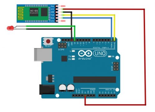
This is how we will have to connect at HC-05 Bluetooth module with Arduino Uno then we will connect the led with the Arduino. The longer leg of the LED which is anode will going to connect to 13 pin of the Arduino and the shorter leg of the LED will going to connect to the ground. Don’t forget to add a current limiting resistor with one of the legs of the LED if incase you are using an LED below 5volts. You can select a 330 ohm resistor, which works perfect with 2.5v LEDS.
In order to make a successful communication, you will need to program the Arduino board. Next, we are going to write a very basic program to read the HC05 Bluetooth module and then control the LED as per the command received from the cell Phone App designed in MIT App Inventor.