- Voice Controlled Home Automation using Arduino and HC-05 Bluetooth Module
- Introduction
- Project Concept
- Block Diagram of Voice Controlled Home Automation
- Components Required
- Circuit Diagram of Voice Control Home Automation using Arduino and Bluetooth Module HC-05
- App Configure
- Working Principle of Voice Control Home Automation using Arduino and Bluetooth Module HC-05
- Arduino Code for Voice Controlled Home Automation
- Голосовое управление светодиодом с помощью Arduino и Bluetooth
- Необходимые компоненты
- Bluetooth модуль HC-06
- Схема проекта
- Объяснение программы для Arduino
- Работа проекта
- Исходный код программы
Voice Controlled Home Automation using Arduino and HC-05 Bluetooth Module

Hello friends! Welcome back to ElectroDuino. This blog is base on Voice Controlled Home Automation using Arduino and HC-05 Bluetooth Module. Here we will discuss Introduction to Voice Controlled Home Automation, Project Concept, Block Diagram, Components Required, Circuit Diagram, Working Principle, and Arduino code.
Introduction
In the previous Home Automation Series, we have learned how to make RF Based, IR Remote Control, Bluetooth Control, and GSM Based home automation systems, where we have controlled home appliances by sending text messages or pressing the button. But, in this project, we will control the AC home appliances by sending Voice Command from our smartphone. We will use a Bluetooth module in our project that helps to connect and communicate with a smartphone wirelessly. Also, we will use a Bluetooth app on our smartphone, which is helping to send our voice Command from our smart phone to the project circuit.
Project Concept
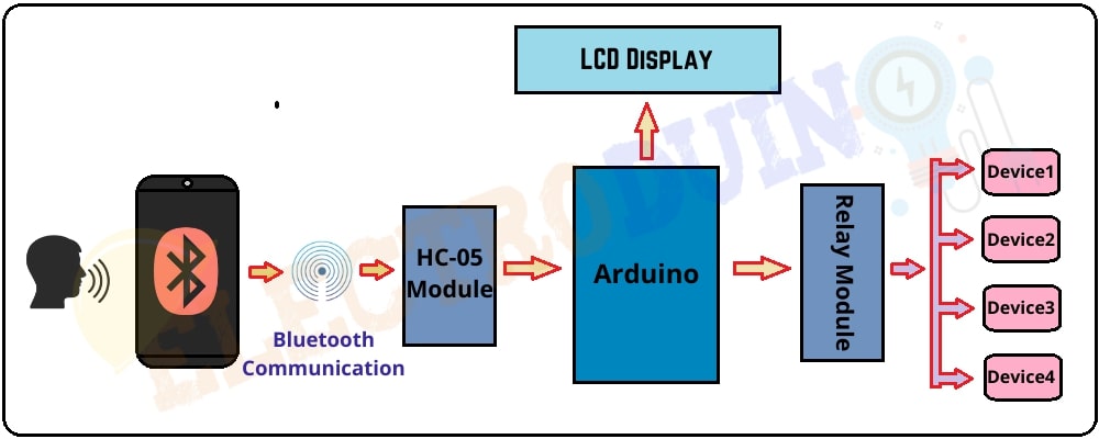
Here we will control four different home appliances by voice Command. The key components of this project are Arduino, Bluetooth module, Relay module, LCD display, a smartphone, and Android App. At first, we need to install the app on our smartphone, which is easily available in the play store. This app receives our Voice command and sends it to the Bluetooth module wirelessly. The Arduino decodes this command from the Bluetooth module. Then Arduino sends a command to the Relays to control the home appliances. These four home appliances are switched on/off by eight different voice commands. The LCD module will display the status of the home appliances on or off.
Block Diagram of Voice Controlled Home Automation
Components Required
| Components Name | Quantity |
| Arduino ( you can use Arduino nano or other types of Arduino board) | 1 |
| HC-05 Bluetooth Module ( you can use the HC-06 Bluetooth Module circuit diagram and the connection is the same) | 1 |
| 4 Channel Relay Module | 1 |
| LCD display module | 1 |
| AC Bulb with Holder and Wire | 4 |
| PCB Prototyping board | 1 |
| 12V DC Power supply | 1 |
| 220V AC Power supply | 1 |
| Connecting wires | As required in the circuit diagram |
| Android Phone | 1 |
| “Bluetooth voice control for Arduino” App | Available in the play store |
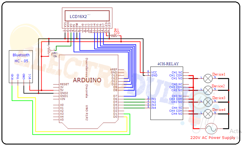
Circuit Diagram of Voice Control Home Automation using Arduino and Bluetooth Module HC-05
App Configure
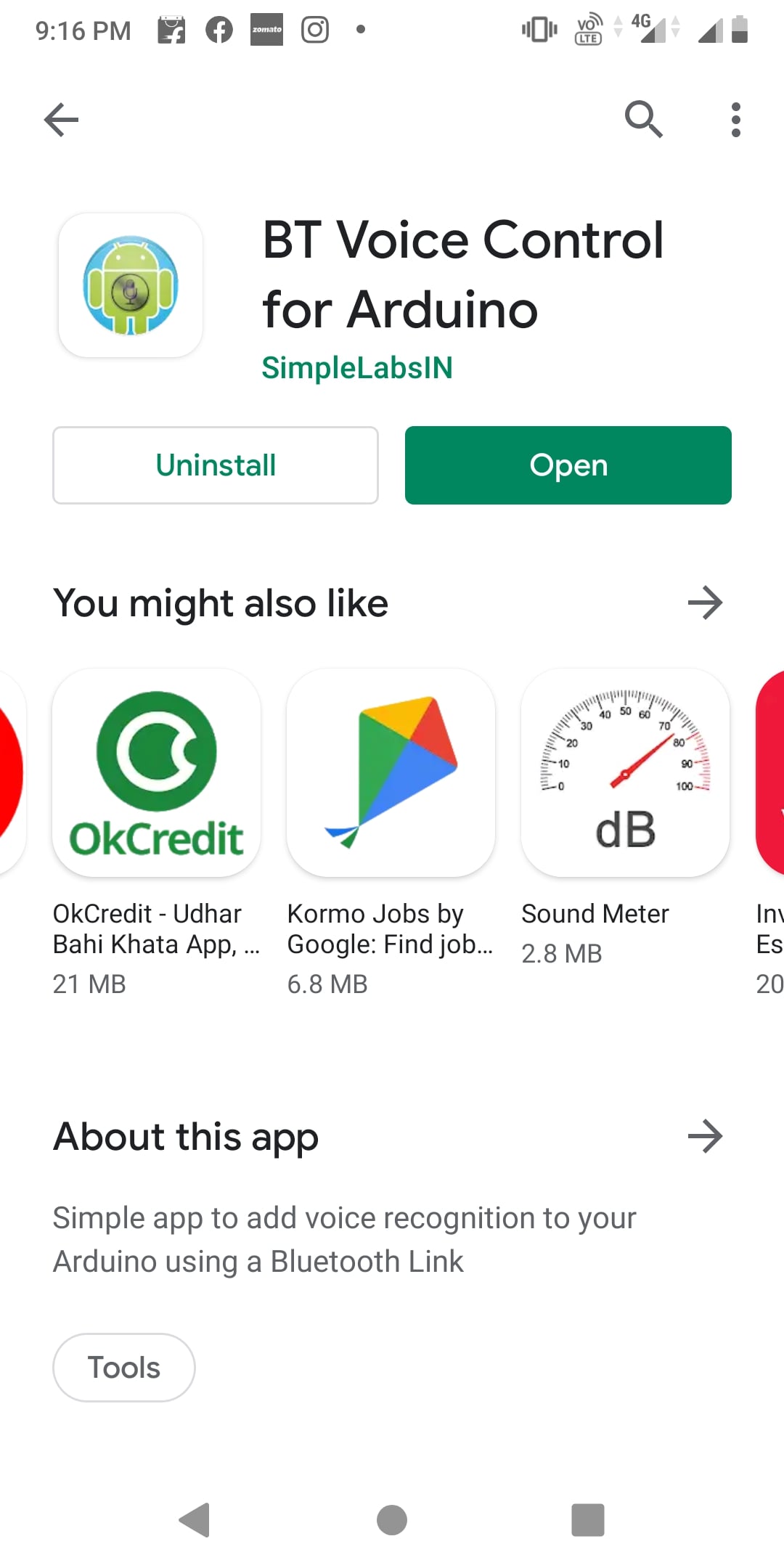
First of all, open the Play Store of your phone and search for “BT Voice Control for Arduino”. Then you will get this app. Now install this app.
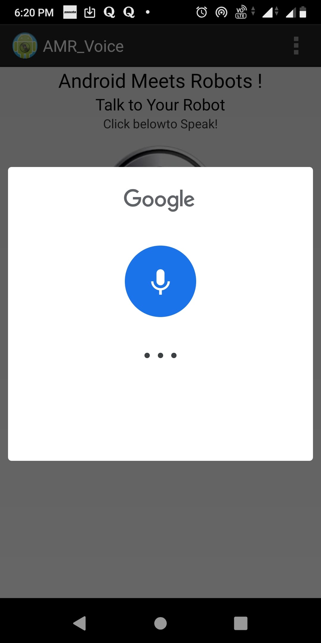
After completing the installation process, open the app and make sure the circuit is connected to the power supply and the Bluetooth module is on. Now click on the mic button to come on the app dashboard.

Now you can see the 3 dots on the top right corner of the app dashboard. Then click on it and select the Connect Robot option. Before doing this make sure, your smartphone has Paired with Bluetooth Module. If it not paired then find the HC-05 Bluetooth module in your phone Bluetooth settings and pair your phone with it. In this case, the HC-05 Bluetooth module asks for a pin code for pairing, usually, the pin code is 1234 or 0000.

After click on the Connect Robot option. Then select the HC-05 for connecting the Bluetooth module with your phone. When this process is successfully completed, then you get the “Connected to HC-05” message on the app dashboard.


Now click on the mic button on the dashboard, then you can send a voice command through the App.
Working Principle of Voice Control Home Automation using Arduino and Bluetooth Module HC-05
At first, we need to choose 8 different types of Voice Commands to control 4 devices. Particular two voice commands are used to control a device. For example, the “turn on light ” command is used to Turn ON the Light, and the “turn off light ” command is used to Turn OFF the Light. These Voice commands are used in Arduino code. The list of voice commands is below, which is used in Arduino code:
| Voice commands | Device status | Control Relay (Relay Pin) |
| turn on light | Light On | Relay-1 (IN1) |
| turn off light | Light Off | |
| turn on fan | Fan On | Relay-2 (IN2) |
| turn off fan | Fan Off | |
| turn on TV | TV On | Relay-3 (IN3) |
| turn off TV | TV Off | |
| turn on pump | Pump On | Relay-4 (IN4) |
| turn off pump | Pump Off | |
| turn on all | All Device On | Relay-1, Relay-2 Relay-3, Relay-4 (IN1, IN2, IN3, IN4) |
| turn off all | All Device Off |
When we send a voice command through the App, then the Bluetooth module receives that command and passes it to the Arduino. Now Arduino compares this command with the predefine Commands (which are defined in Arduino code). If this command matches then Arduino sends a command to operate the relay module. We can see the Device status (on or off) on the 16×2 LCD Display Module.
For example, when we send the “turn on light” voice command through the app. Then the Arduino gets this command through the Bluetooth module. Then the Arduino sends Low (0) input voltage to the Input-1 (IN1) pin of the relay module. Now the relay is in On mode. So the device (light) will also turn on, which is connected to the relay-1 of the relay module. At the same time, the “D1 (Device 1) is ON” status print on the 16×2 LCD Display Module.
When we send the “ turn off light” voice command through the app. Again the Arduino gets this command through the Bluetooth module. This time the Arduino sends a High (5v) input voltage to the Input-1(IN1) pin of the relay module. Now the relay is in Off mode. So the device (light) will also turn off, which is connected to the relay-1 of the relay module. At the same time, the “D1 (Device 1) is OFF” status print on the 16×2 LCD Display Module.
In this way, we can control all relays of the 4 channel Relay module through the voice command
Arduino Code for Voice Controlled Home Automation
//libraries for LCD Display #include // Define LCD display pins LiquidCrystal lcd(12,11,10,9,8,7); // DeUfine 4 channel relay pins const int Light = 6; // Relay pin 1 (IN1) const int Fan = 5; // Relay pin 2 (IN2) const int TV = 4; // Relay pin 3 (IN3) const int Pump = 3; // Relay pin 4 (IN4) String data; //Variable for storing received data void setup() < Serial.begin(9600); //Sets the baud for serial data transmission // Set Relay pins as OUTPUT pinMode(Light, OUTPUT); pinMode(Fan, OUTPUT); pinMode(TV, OUTPUT); pinMode(Pump, OUTPUT); // Print massage on LCD Display lcd.begin(16, 2); lcd.setCursor(0,0); lcd.print("Voice Controlled"); lcd.setCursor(0,1); lcd.print("Home Automation"); delay(2000); // All devics are Off when system is on digitalWrite(Light, HIGH); digitalWrite(Fan, HIGH); digitalWrite(TV, HIGH); digitalWrite(Pump, HIGH); // Print Device status (all Off) on LCD Display lcd.clear(); lcd.setCursor(0,0); lcd.print(" D1 D2 D3 D4 "); lcd.setCursor(0,1); lcd.print("OFF OFF OFF OFF"); >void loop() < // Read data from Bluetooth Module char ch=0; data=""; while(1) < while(Serial.available()<=0); ch = Serial.read(); if(ch=='#') break; data+=ch; >// Print Bluetooth Module data on serial monitor Serial.print(data); Serial.print("\n"); // Control the devices using voice command if (data == "*turn on light") // turn on Device1 < digitalWrite(Light, LOW); lcd.setCursor(0,1); lcd.print("ON "); delay(200); >else if (data== "*turn off light") // turn off Device1 < digitalWrite(Light, HIGH); lcd.setCursor(0,1); lcd.print("OFF"); delay(200); >else if (data== "*turn on fan" ) // turn on Device2 < digitalWrite(Fan, LOW); lcd.setCursor(4,1); lcd.print("ON "); delay(200); >else if (data== "*turn off fan" ) // turn off Device2 < digitalWrite(Fan, HIGH); lcd.setCursor(4,1); lcd.print("OFF"); delay(200); >else if (data== "*turn on TV" ) // turn on Device3 < digitalWrite(TV, LOW); lcd.setCursor(9,1); lcd.print("ON"); delay(200); >else if (data== "*turn off TV" ) // turn off Device3 < digitalWrite(TV, HIGH); lcd.setCursor(9,1); lcd.print("OFF"); delay(200); >else if (data== "*turn on pump" ) // turn on Device4 < digitalWrite(Pump, LOW); lcd.setCursor(13,1); lcd.print("ON "); delay(200); >else if (data== "*turn off pump" ) // turn off Device4 < digitalWrite(Pump, HIGH); lcd.setCursor(13,1); lcd.print("OFF"); delay(200); >else if (data== "*turn on all" ) // turn on all Device < digitalWrite(Light, LOW); digitalWrite(Fan, LOW); digitalWrite(TV, LOW); digitalWrite(Pump, LOW); lcd.setCursor(0,1); lcd.print("ON ON ON ON "); delay(200); >else if (data== "*turn off all" ) // turn off all Device < digitalWrite(Light, HIGH); digitalWrite(Fan, HIGH); digitalWrite(TV, HIGH); digitalWrite(Pump, HIGH); lcd.setCursor(0,1); lcd.print("OFF OFF OFF OFF"); delay(200); >> Голосовое управление светодиодом с помощью Arduino и Bluetooth
На первый взгляд, управление светодиодом с помощью голоса может показаться достаточно трудной задачей, но с помощью такой платформы как Arduino в этом нет ничего сложного. Все, что нам нужно будет сделать – это соединить плату Arduino по последовательному каналу связи с Bluetooth модулем HC-06 и с помощью смартфона передавать голосовые команды на Bluetooth модуль HC-06. Для приема голосовых команд мы будем использовать приложение на android “Arduino Bluetooth Voice Controller”, которое можно будет скачать по ниже приведенной ссылке.

Необходимые компоненты
- Плата Arduino Uno (купить на AliExpress).
- Bluetooth модуль HC-06 (купить на AliExpress).
- Красный и зеленый светодиоды (купить на AliExpress).
- Резистор 220 Ом (2 шт.) (купить на AliExpress).
- Arduino Bluetooth Voice Controller (можно скачать с play store по этой ссылке или непосредственно скачать прямо из смартфона по названию приложения).
- Макетная плата.
- Соединительные провода.
Bluetooth модуль HC-06
Данный модуль может функционировать в двух режимах: режим команд и режим данных. В режиме команд мы можем настраивать различные свойства Bluetooth соединения: имя, пароль, скорость передачи и т.д. Режим данных позволяет осуществлять обмен данными между модулем и микроконтроллером (в нашем случае платой Arduino). Мы в данном проекте будем использовать только режим данных, свойства Bluetooth соединения будем использовать те, которые установлены в модуле по умолчанию. Имя устройства может быть HC-05 или HC-06 (в использованном нами модуле), пароль может быть 0000 или 1234, по умолчанию скорость передачи обычно выставлена 9600 бод/с.
Модуль работает от питающего напряжения 5V, а его сигнальные контакты работают с напряжением 3.3V. В модуле присутствует встроенный регулятор напряжения, поэтому нам не стоит беспокоиться о преобразовании этих напряжений. В режиме данных мы из 6 контактов модуля будем использовать только 4. Назначение контактов Bluetooth модуля HC-06 приведено в следующей таблице.
| № по порядку | Назначение контакта |
| 1 | Vcc |
| 2 | Vcc |
| 3 | Tx |
| 4 | Rx |
| 5 | State |
| 6 | EN (Enable) |
На нашем сайте вы также можете следующие проекты с использованием Bluetooth модуля:
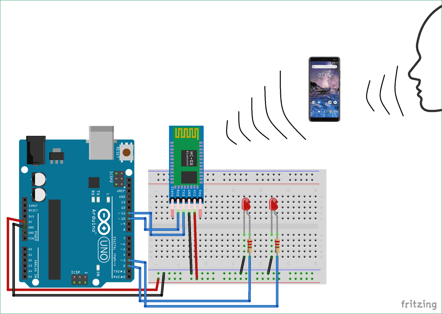
Схема проекта
Схема голосового управления светодиодом с помощью Arduino и Bluetooth представлена на следующем рисунке. Перед загрузкой программы в плату Arduino отсоедините контакты Rx и Tx, а после загрузки программы снова их подсоедините.
 Объяснение программы для Arduino
Полный код программы приведен в конце статьи, здесь же мы рассмотрим его наиболее важные фрагменты.
Сначала в программе необходимо определить контакты Arduino, на которых мы будем использовать последовательную связь (Rx и Tx).
Затем установим 2-й и 3-й контакты платы Arduino (к ним подключены светодиоды) в режим вывода данных.
Далее, в функции loop плата Arduino будет непрерывно проверять поступление данных от Bluetooth модуля (который, в свою очередь управляется с помощью голосовых команд) и в соответствии с ними управлять включением/выключением светодиодов. Все принимаемые команды мы будем сохранять в переменной “Value”.
Если значение этой переменной равно «all LED turn on», то мы будем включать оба светодиода. Аналогично этому при поступлении других голосовых команд мы будем соответствующим образом включать и выключать светодиоды в нашей схеме. Более подробно все эти процессы показаны на видео, приведенном в конце статьи.
Работа проекта

Шаг 1. Соберите схему, приведенную на рисунке выше. Перед загрузкой кода программы в плату Arduino отсоедините контакты Rx и Tx. После загрузки программы снова их подсоедините.
Шаг 2. Скачайте по приведенной в начале статье ссылки приложение для смартфона под названием “Arduino Bluetooth Voice Controller”. Либо вы непосредственно можете скачать его со своего смартфона по его названию.
Шаг 3. Запустите скачанное приложение, у вас на смартфоне появится его экран, показанный на приведенном ниже рисунке. Кликните на “connect to Bluetooth device” (соединиться с Bluetooth устройством), выберите после этого свой Bluetooth модуль и затем проверьте подсоединился ли он к приложению или нет. Затем кликните на иконку микрофона и после этого вы можете передавать голосовые команды Bluetooth модулю HC-06.
Примечание : когда вы будете подключаться к Bluetooth модулю HC-06 в первый вам необходимо будет ввести пароль для подключения к модулю – используйте в качестве пароля 0000 или 1234.
Шаг 4. Передавая голосовые команды Bluetooth модулю HC-06, который затем транслирует их по последовательному порту связи плате Arduino, которая выполняет принятую команду по включению/выключению светодиодов. Список реализованных в программе команд и действия, которые при их поступлении следует выполнить, представлен в следующей таблице.
| № п/п | Команда | Действие |
| 1 | all LED turn on | включить оба светодиода |
| 2 | all LED turn off | выключить оба светодиода |
| 3 | turn on Red LED | включить красный светодиод |
| 4 | turn on green LED | включить зеленый светодиод |
| 5 | turn off red LED | выключить красный светодиод |
| 6 | turn off green LED | выключить зеленый светодиод |
Аналогичным образом, изменяя код программы, вы можете добавить в этот проект любые другие команды и, соответственно, добавить в схему любые другие устройства (электрическая лампочка, телевизор, кондиционер и т.д.), которыми вы хотите управлять с помощью голоса.
Примечание : статья переведена с иностранного сайта и насколько корректно представленное приложение “Arduino Bluetooth Voice Controller” и программа для Arduino может работать со словами на русском языке, лично я пока не пробовал. Но буду признателен если вы в комментариях к данной статье отпишитесь по этому поводу если попробуете сделать это.
Исходный код программы
Если у вас возникнут какие либо вопросы по тексту данной программы, то вы можете задать их в комментариях к данной статье, постараюсь ответить.