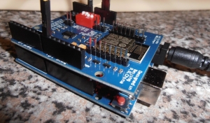
UNO R3 + WIFI ESP8266 + CH340G Arduino and WIFI single board
This specific development board has numerous advantages (which will be covered later) but lacks comprehensive documentation. This surprising because it would seem the ideal development platform for WiFi enabled Arduino projects. Hopefully this project can help with providing more details.
The Arduino ESP8266 WIFI development board
A search for the following text “UNO R3 WIFI ESP8266 ATMEGA328 CH340G” will yield numerous results of sites that sell this particular development board. It can be found on eBay, AliExpress, Banggood and other sites. Cost is approximately 10 to 14 USD before shipping. Before purchasing, make sure that the photograph in this article matches the picture on the selling site.
High level specifications of the board as follows:
- Model Number: UNO+WiFi-R3-AT328-ESP8266-32MB-CH340G
- Supply Voltage: 6 to 9V
- CPU: ATmega328
- WiFi: ESP8266
- USB- TTL converter: CH340G
- Header PinOut: Uno R3
A description of the components on the board in the image below:
Some notes on the components:
- The board includes a 5V and 3.3 V Voltage regulator to allow for the differing voltage requirements for the ESP8266 and ATMega328
- Instead of the large USB connector used on a standard Arduino, this board uses a micro USB connector for serial communication and programming
- The Reset button rests both the ESP 8266 and ATMega328
- The header pin out is standard Arduino; this allows any Arduino compatible shield to be connected to this development board
- The board includes a small WiFi antenna. If greater range is required, provision is made for connecting an external antenna
Advantages of The Arduino ESP8266 WIFI development board
It seems that this specific board has several advantages over similar solutions (specifically the WeMos D1 board)
The Arduino pin out allows for connection of many of the Arduino shields available
The different voltage levels are built into the board and become transparent to the User
It allows for easy implementation of WiFi communication in Arduino projects
As there are two processors incorporated on the board, a greater range of processing power is available
Communication between the ATMega328 and the ESP8266 is via the serial lines and utilizes the well known Serial library
Crucial to the operation of the board is the Mode Selection switch, consisting of a 8 switch DIP mounted in the center of the board.
The mode switch allows for four possible settings
Mode 1 – USB Serial connected to ATMega328 for both programming and serial communication
Mode 2 – USB Serial connected to ESP8266 for programming
Mode 3 – USB Serial connected to ESP8266 for serial communication
Mode 4 – ATMega328 and ESP8266 serial connected together, allowing for serial communication between the two devices. The voltage difference between the Arduino and ESP8266 is taken care of in the board.
The ESP8266 requires that GPIO0 is pulled to ground while programming, a requirement not applicable to the ATMega328. Hence there are two separate modes for the ESP8266; switching SW7 on grounds GPIO0.
The DIP switch settings for these modes in the following table:
DIP Switch settings for various modes. X = Switch On Blank = Switch Off
The board has a legend showing the switch settings.
Programming the ATMega328
As a first demonstration, we can program the ATMega328 with the Blink Sketch. Steps as follows:
- Disconnect the board from power
- Using a paper clip or pencil point (or any other sharp end device), set the switches to Mode 1. This means that SW3 and SW4 are On, all other switches are off.
- Call up the Blink Sketch in the Arduino IDE from Examples → Basic
- Connect the Micro USB port to your computer with a USB to Micro USB cable
- Upload the Sketch
The ATMega328 will automatically reset and the LED labeled “L” will start blinking.
Success, the ATMega328 is working and can be programmed. Simple.
This part is a little more complicated.
Before programming the ESP8266, you have to ensure that the Arduino IDE you are using is configured to do this type of programming. There are numerous articles on the Internet explaining how to do this. A search of “program ESP8266 from Arduino IDE” will provide many results.
The basic steps are as follows:
- In File → Preferences, add a url to the Additional Boards Manager: http://arduino.esp8266.com/stable/package_esp8266com_index.json
- Under Tools → Boards → Boards Manager, Search for ESP8266 and install latest version of “ESP8266 by ESP8266 Community”
- Once this is done, you should have an option under Tools→ Board for a ESP8266 Boards. Choose Generic ESP8266 Module.
After all that you are ready to get a Blink program working on the board. There appears to be no built in LED for the ESP8266 on this board, so you have to connect an LED to demonstrate the blink program.
The ESP header on the board allows access to GPIO12 from the ESP8266, this will be used for connecting the LED. The pin functions are given on the rear of the board. Connect a 330 Ohm (or similar) and LED wired in series between GPIO12 and the GND pin on the Arduino header.
Follow the following steps:
- Make sure the Arduino IDE is set for the Generic ESP8266 Module
- Remove power from the board. Set the switches to Mode 2. This means that SW5, SW6, SW7 are On. all other switches are Off.
- Connect the Micro USB port to your computer with a USB to Micro USB cable
- Upload the Sketch Blink ESP8266
/*
 ESP8266 Blink
 Blink the LED on the ESP8266 module
 This example code is in the public domain

 The external LED on the ESP8266 module is connected to GPIO12

*/

void setup()
 pinMode(12, OUTPUT); // Initialize pin 12 which is GPIO12 as an output
>

// the loop function runs over and over again forever
void loop()
 digitalWrite(12, LOW); // Turn the LED off
 // low is off on the ESP8266-12
 delay(1000); // Wait for a second
 digitalWrite(12, HIGH); // Turn the LED on by making the voltage HIGH
 delay(2000); // Wait for two seconds (to distinguish between low and high)
>
bool toggle;
String incomingString;
void setup()
pinMode(12, OUTPUT); // Initialize pin 12 which is GPIO12 as an output
toggle = false;
Serial.begin(115200); //All serial communication with ESP8266 at 115200 baud
>
void loop()
if (Serial.available() > 0)
// read the incoming string from the Arduino
incomingString = Serial.readString();
// If the incoming string from the Arduino equals "change" then we toggle the LED
if (incomingString.equals("change"))
digitalWrite(12, toggle); // Turn the LED off or on
toggle = !toggle;
>
>
delay(50); // Wait for half second
>If successful, the Arduino IDE will produce the following message – “Hard resetting via the RTS pin”
Remove power from the board and toggle SW7 to off. This takes the ESP8266 out of programming mode.
Restore power to the board and the LED connected to GPIO12 should start blinking. Success!
Communicating between the ATMega328and ESP8266
The ATMega328 and ESP8266 can communicate via the serial bus include in both chips. This communication is bilateral; ATMega826 can send information to the ESP8266 and vice versa.
To demonstrate this, a simple circuit connected to the ATMega328 can activate an LED connected to the ESP8266. Circuit diagram below.
The programming steps as follows.
- Set the DIP switch to Mode 1 (SW3 and SW4 are On )with power removed. Restore power and upload the Arduino Sketch “ArduinoESPCommunication
- Remove power and set the DIP switch to Mode 2 (SW5, SW6, SW7 are On)
- Change Arduino IDE to ESP8266 programming mode and upload the sketch “ESPRecieveCommunication”
- Remove power and set the dip switch to Mode 4 (SW1 and SW2 are On)
- Restore power
const int buttonPin = 2; // the number of the pushbutton pin
int buttonState = 0;
void setup()

// Initialize the pushbutton pin as an input:
 pinMode(buttonPin, INPUT);
 pinMode(LED_BUILTIN, OUTPUT);

 Serial.begin(115200); //All ESP8266 serial communication at 115200 baud
>

void loop()
 // read the state of the pushbutton value:
 buttonState = digitalRead(buttonPin);

 // check if the pushbutton is pressed. If it is, the buttonState is HIGH:
 if (buttonState == HIGH)
 // Send a message to the ESP8266
 Serial.write("change");
 // Flash the built in LED to confirm that button push was registered
 digitalWrite(LED_BUILTIN, HIGH); // turn the LED on (HIGH is the voltage level)
 delay(500);
 digitalWrite(LED_BUILTIN, LOW); // turn the LED off by making the voltage LOW
 delay(250);

 >
 else
 delay(25);
 >
>
Pressing the push button will cause the ATMega328 built in LED to flash and the LED connected to the ESP8266 will come on.
Pressing the push button again will flash the built in LED and turn off the LED connected to the ESP8266
Communication between the ATMega328 and the ESP8266 uses the Serial.write(“change”) and Serial.readString() commands. See the sketches for more details.
It is uncertain why this specific development board is not more popular (based on the number of articles and documentation available on line). It has several advantages over trying to implement an Arduino with a separate ESP8266 board and provides dual processing power.
Good luck using this board!
Используем Arduino UNO с WiFi на одной плате для POST запроса на сервер
В статье «Как у меня заработал WIFI для Arduino ESP8266 ESP-12E» рассказывал как заставить работать платы Arduino UNO с ESP8266 ESP-12E UART Wi-Fi.
Но зачем такие сложности, если есть уже совмещенная плата?
Вместо слоеного пирога из двух плат:
И она заработала безо всяких прошивок и перепрошивок.
Работает только на скорости 115200
Среда Arduino уже была настроена для работы.
Осталось только переключатели перещелкивать, чтобы заливать скетч в UNO.
Таблица положений переключателей есть здесь.
Вот только не упомянуто положение переключателей (1-4 ON), когда во время работы Mega328+ESP8266 CH340 мониторит порт и выводит в консоль передаваемые команды.
Как настроить среду Arduino объясняется здесь или здесь.
Таблица переключателей.
CH340 connect to ESP8266 (upload sketch)
CH340 connect to ESP8266 (connect)
CH340 connect to ATmega328 (upload sketch)
All modules work independent
Совместная работа и мониторинг команд
Передача информации на серверы Cayenne и RemoteXY.
Протестировал плату на решении задач, скетчи которых заливал в слоеный пирог из двух плат:
Эти сервисы предоставляют свои библиотеки для работы с ESP8266.
Все заработало сразу без изменений и мучений.
Необходимо в скетчах заменить скорость на 115200.
Передача информации на произвольный сервер.
Решение предыдущей задачи «Отправка данных из ESP8266WiFi на сервер с CMS MaxSite» с этой платой повторить не удалось.
Для отправки данных на произвольный сервис использовалась универсальная библиотека WiFiESP.
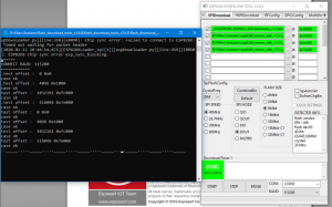
И оказалось, что эта библиотека не заработала с этой платой, выдавая
[WiFiEsp] Warning: Unsupported firmware 0.9.5
Действительно, модуль при обращении с соответствующей командой AT+GMR сообщает версию SDK 0.9.5:
В файле README.md библиотеки можно прочитать:
Попытки обновить прошивку при помощи flash_download_tools не увенчались успехом (да и не старался особо):
Ведь библиотеки Cayenne и RemoteXY для этой платы заработали без проблем!
В этих статьях описывается способ обращения к ESP8266 обычными командами без библиотек.
Будем обрабатывать POST запрос к серверу при помощи плагина my_esp8266 для MaxSiteCMS, который принимает данные.
Заработал вот такой скетч.
// отсылает данные в плагин http://fil-tec.ru/tag/My_ESP8266 для MaxSite CMS String ssid ="Router name"; String password="**********"; String server = "my.site.ru"; // сайт, на котором установлен пагин My_esp8266 String uri = "/ajax/**************************"; // скопировать со страницы "Тест" админки плагина My_esp8266 адрес для обращения с запросами String PORT = "80"; int countTrueCommand; int countTimeCommand; boolean found = false; int valSensor = 1; String jsonString; // данные String PostHeader; // заголовок String data; int DHpin = 4; //sensor pin byte dat [5]; String temp ,hum; #define PIN_SWITCH_1 12 #define PIN_SWITCH_2 13 void setup() < pinMode (DHpin, OUTPUT); pinMode (PIN_SWITCH_1, OUTPUT); pinMode (PIN_SWITCH_2, OUTPUT); Serial.begin(115200); reset(); connectWifi(); >void reset() < Serial.println("AT+RST"); delay(1000); >//connect to your wifi network void connectWifi() < Serial.begin(115200); sendCommand("AT", 5, "OK"); sendCommand("AT+CWMODE=1", 5, "OK"); sendCommand("AT+CWJAP=\"" + ssid + "\",\"" + password + "\"", 20, "OK"); digitalWrite(PIN_SWITCH_2, (found == true)?LOW:HIGH); >byte read_data () < byte data; for (int i = 0; i < 8; i ++) < if (digitalRead (DHpin) == LOW) < while (digitalRead (DHpin) == LOW); // wait for 50us delayMicroseconds (30); // determine the duration of the high level to determine the data is '0 'or '1' if (digitalRead (DHpin) == HIGH) data |= (1 > return data; > void start_test () < digitalWrite (DHpin, LOW); // bus down, send start signal delay (30); // delay greater than 18ms, so DHT11 start signal can be detected digitalWrite (DHpin, HIGH); delayMicroseconds (40); // Wait for DHT11 response pinMode (DHpin, INPUT); while (digitalRead (DHpin) == HIGH); delayMicroseconds (80); // DHT11 response, pulled the bus 80us if (digitalRead (DHpin) == LOW); delayMicroseconds (80); // DHT11 80us after the bus pulled to start sending data for (int i = 0; i < 4; i ++) // receive temperature and humidity data, the parity bit is not considered < Serial.println(i); dat[i] = read_data (); >pinMode (DHpin, OUTPUT); digitalWrite (DHpin, HIGH); // send data once after releasing the bus, wait for the host to open the next Start signal > void loop () < start_test (); // convert the bit data to string form hum = String(dat[0]); temp= String(dat[2]); jsonString = "secret=0000&name=ESP_8266WiFi&temp=" + temp + "&hum=" + hum; httppost(); delay(1000); >void httppost () < String postRequest = "POST " + uri + " HTTP/1.1\r\n" + "Host: " + server + "\r\n" + "User-Agent: ESP8266WiFi\r\n" + "Accept: application/xml\r\n" + "X-Requested-With: XMLHttpRequest\r\n" + "Referer: http://my.site.ru\r\n" + "Connection: close\r\n" + "Content-Length: " + jsonString.length() + "\r\n" + "Content-Type: application/x-www-form-urlencoded\r\n" + "\r\n" + jsonString; sendCommand("AT+CIPMUX=1", 5, "OK"); sendCommand("AT+CIPSTART=0,\"TCP\",\"" + server + "\"," + PORT, 15, "OK"); sendCommand("AT+CIPSEND=0," + String(postRequest.length() + 2), 4, ">"); sendCommand(postRequest, 5, "OK"); delay(1500); countTrueCommand++; sendCommand("AT+CIPCLOSE=0", 5, "OK"); > void sendCommand(String command, int maxTime, char readReplay[]) < while (countTimeCommand < (maxTime * 1)) < Serial.println(command);//at+cipsend delay(1500); if (Serial.find(readReplay)) //ok < found = true; break; >countTimeCommand++; > if (found == true) < // успешно digitalWrite(PIN_SWITCH_1, LOW); countTrueCommand++; countTimeCommand = 0; >if (found == false) < // неудачно digitalWrite(PIN_SWITCH_1, HIGH); countTrueCommand = 0; countTimeCommand = 0; >found = false; >