Arduino.ru


Плата расширения Arduino WiFi позволяет контроллерам Arduino осуществлять сетевое соединение, используя беспроводную сеть формата 802.11. Плата построена на базе чипа HDG104 Wireless LAN 802.11b/g System in-Package. Микроконтроллер Atmega 32UC3 обеспечивает поддержку сетевого стэка (IP) как для TCP, так и для UDP протокола. Разработчики рекомендуют использовать библиотеку WiFI для работы с данной платой.
Физически плата WiFi, как и большинство плат расширения, соединяется с платой контроллера Arduino посредством контактных колодок, расположенных по краям платы. Размеры соответствуют контактам на контроллерах Arduino UNO и Arduino Mega2560.
На плате WiFi имеется слот для micro-SD карт, которые могут быть использованы для хранения и передачи файлов по сети. Для доступа к данным на карте можно использовать библиотеку SD Library. SS (выбор ведомого) для SD слота находится на порту вход/выхода 4, что следует учитывать при работе с этой библиотекой.
Соединение Arduino контроллера с процессором платы расширения WiFi и встроенной картой SD осуществляется по SPI шине на разъеме ICSP. При этом задействованы следущие выходы: 11, 12 и 13 на UNO и выходы 50, 51 и 52 на Mega. На обоих платах выход 10 используется для выбора HDG104 и выход 4 для SD карты. Эти вход/выходы не могут быть задействованы для других целей. На контроллере Mega выход 53 (SS), не используется для выбора ведомого устройства HDG104, либо SD карты, но должен оставаться OUTPUT иначе будет нарушена работа SPI интерфейса.
Порт 7 используется для синхронизации (handshake) между платой WiFi и Arduino и не может быть задействован для других целей.

Обратите внимание, что посколько HDG104 и слот SD карты делят шину SPI, они не могут быть использованы одновременно. Имейте это ввиду при использовании соответствующих библиотек. Если вы не используете одно из устройств, вам необходимо принудительно отключить его. Для отключения SD карты, установить порт 4 в OUTPUT и HIGH, для отключения HDG104 — порт вход/выхода 10 в OUTPUT, HIGH.
Плата WiFi может быть использована как в открытых беспроводных сетях, так и в сетях с использованием шифрования WPA2 Personal, либо WEP. Для успешного соединения точка доступа должна анонсировать SSID.
Кнопка сброса (reset), перезагружает процессор на плате WiFi и одновременно контроллер Arduino.

На плате расширения распаян коннектор Mini-USB, который используется для перепрошивки Atmega 32U с использованием протокола Atmel DFU. Перемычка (джампер) DFU осуществляет перевод платы в режим прошивки, в остальных случаях она должна быть незамкнута.
Коннектор FTDI может быть использован для последовательного соединения с микроконтроллером 32U для отладки. Список доступных команд.
Также на плате есть несколько светодиодов:
- L9 (желтый) : поключен к выходу 9
- LINK (зеленый) : отображает статус соединения с сетью
- ERROR (красный) : загорается при ошибке соединения
- DATA (синий) : показывает процесс приема/передачи данных по сети
Arduino WiFi Shield 101
The Arduino WiFi Shield 101 is a powerful IoT shield with crypto-authentication which allows you to wirelessly connect your Arduino or Genuino with ease. This shield is perfect for your IoT projects!
LAST REVISION: 07/13/2023, 08:02 AM
Note: This page refers to a product that is retired.
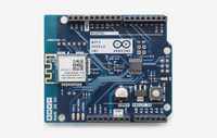
Arduino WiFi Shield 101 is a powerful IoT shield with crypto-authentication, developed with ATMEL, that connects your Arduino or Genuino board to the internet wirelessly. Connecting it to a WiFi network is simple, no further configuration in addition to the SSID and the password are required. The WiFi 101 Shield comes with an easy-to-use library that allows to connect your Arduino or Genuino board to the internet with few instructions. As always, every element of the platform – hardware, software and documentation – are freely available and open-source. This means that you can learn exactly how it’s made and use its design as the starting point for your own projects.
- Operating voltage both 3.3V and 5V (supplied from the host board)
- Connection via: IEEE 802.11 b/g/n for up to 72 Mbps networks
- Encryption types: WEP and WPA2 Personal
- Support TLS 1.1 (SHA256)
- Connection with Arduino or Genuino on SPI port
- Onboard CryptoAuthentication by ATMEL
You can find here your board warranty information.
The WiFi Shield 101 needs certificates to ensure SSL connection. To upload new certificates and update the firmware, please refer to the Utilities section in the WiFi101 Library reference.
Getting Started
You can find in the Getting Started section all the information you need to configure your board, use the Arduino Software (IDE), and start tinker with coding and electronics.
Need Help?
Documentation
OSH: Schematics
The Arduino WiFi Shield 101 is open-source hardware! You can build your own board using the following files:
The Arduino WiFi Shield 101 allows an Arduino or Genuino board to connect to the internet using the IEEE 802.11 wireless specifications (WiFi). It is based on the Atmel SmartConnect-WINC1500 module, compliant with the IEEE 802.11 b/g/n standard. The WINC1500 module provided is a network controller capable of both TCP and UDP protocols. Use the WiFI library to write sketches which connect to the internet using the shield. The WiFI shield connects to an Arduino or Genuino board using long wire-wrap headers which extend through the shield. This keeps the pin layout intact and allows another shield to be stacked on top.
The WiFi Shield 101 also features an hardware encryption/decryption security protocol provided by the ATECC508A CryptoAuthentication chip that is an ultra secure method to provide key agreement for encryption/decryption, specifically designed for the IoT market.
Digital pin 7 is used as a handshake pin between the WiFi 101 Shield and the board, and should not be used.
Digital pin 5 is used as RESET pin between the WiFi 101 Shield and the board, and should not be used.
Usage with Arduino/Genuino UNO board
Please note that Uno + WiFi Shield 101 is not compatible with the Software Serial library.
The WiFi Shield 101 carries a library that is very complex and occupies more than 60% of the available memory, leaving little room for sketches.
Please keep in mind even if that basic usage is supported for the Uno, for complex projects we strongly recommend to use the WiFi Shield 101 with a Arduino/Genuino Zero, 101 or Mega 2560.
| Example MQTT (complex) | Example WiFi Web Server (easy) | |
|---|---|---|
| UNO | 87% | 76% |
| 101 | 48% | 27% |
| MEGA 2560 | 11% | 10% |
| ZERO | 9% | 8% |
For a better understanding, the table above shows the memory usage (in %) of two different sketches (Example MQTT and WiFi Web Server) on a Uno, Mega 2560, Zero and 101 board.
On-board Indicators
The shield contains a number of signalling LEDs:
- ON (green): indicates that the shield is properly powered
- WIFI (green): indicates a connection to a network
- ERROR (red): indicates when there is a communication error
- NETWORK (yellow): indicates that data is received/transmitted
Arduino UNO R4 Shield Guide

This article covers the basic steps for developing your own shield for the Arduino UNO R4 Minima and the UNO R4 WiFi.
AUTHOR: Hannes Siebeneicher
The Arduino UNO family and its form factor have become a type of standard in the maker scene and remain one of the world’s most popular form factors.
Over the years, a wide range of accessories such as shields and sensors have been made, and in this guide, you will find information that will help you create your own customized hardware for the UNO family.
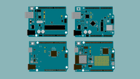
This guide focuses mainly on making accessories for the UNO R4 Minima & WiFi boards. In case you want to design a shield for another UNO make sure to check the respective data sheet and documentation.
Documentation
Each UNO Family board has a dedicated documentation page, see the list below:
Inside the documentation page, you will find design files such as full pinout, CAD, and Fritzing files. You will also find tutorials and compatible libraries with the respective boards on the page.
Technical Overview
Dimensions
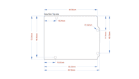
The following dimensions apply to all UNO boards.
| Format | Measurement |
|---|---|
| Width | 53.34 mm |
| Length | 68.58 mm |
| Thickness | 1.6 mm |
| Pitch | 2.54 mm |
Pitch is the space between the pins (e.g. between A1, A2). This specification is important when choosing header pins.
Pinout
Below you can find the pinout for the Arduino UNO R4 Minima. All UNO boards largely share the placement of many pins, to make it easy for accessories to be designed for different UNO boards but if you create accessories for an older UNO be sure to check its respective pinout.
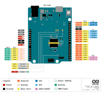
For more information about each pin be sure to check out the advanced section in the pinout which you can see here.
For other UNO boards check the respective documentation page.
Feature Comparisons
Below is a comparison between the different UNO Family boards.
| Board | UNO R3 | UNO R3 SMD | UNO WiFi Rev2 | UNO R4 Minima | UNO R4 WiFi |
|---|---|---|---|---|---|
| Processor | ATmega328P | ATmega328P | ATmega4809 | Renesas RA4M1 | Renesas RA4M1 |
| Connectivity | x | x | Wi-Fi® | x | Wi-Fi®, Bluetooth® |
| Clock Speed | 16 Mhz | 16 Mhz | 16 Mhz | 48 Mhz | 48 Mhz |
| Flash Memory | 32 KB | 32 KB | 48 KB | 256 KB | 256 KB |
| SRAM | 2 KB | 2 KB | 6 KB | 32 KB | 32 KB |
| I/O Voltage | 5 V | 5 V | 5 V | 5 V | 5 V |
Power Considerations
Voltage
Both the UNO R4 Minima and UNO R4 WiFi operate at 5 V. This means connecting 3.3 V peripherals directly may lead to potential issues. Most 3.3 V peripherals expect a 3.3 V logic level for proper operation. One common method is to use level shifters or voltage dividers to convert the 5 V signals to 3.3 V.
This only holds true for the signal pin of a sensor and if the goal is to simply connect a 3.3 V power line the UNO R4 boards still provide a 3.3 V pin that can safely be used with sensors needing that lower power input.
VIN Min/Max
The min/max voltage supply varies between boards. This is important to consider when choosing the battery source, that you do not exceed the limits to damage the board.
| UNO R3 | UNO R3 SMD | UNO WiFi Rev2 | UNO R4 Minima | UNO R4 WiFi |
|---|---|---|---|---|
| 7-12 V | 7-12 V | 6-20 V | 6-24 V | 6-24 V |
Serial Buses
The UNO R4 boards have serial buses attached to the following pins:
| Protocol | Pins |
|---|---|
| UART | RX, TX |
| SPI | COPI (11), CIPO (12), SCK (13), CS(10) |
| I2C | D14 (SDA), D15 (SCL) or A4 (SDA), A5 (SCL) |

The location of these pins is located in the pinout for each board. These are found in the Resources Section product page of each board.
Building Your Shield
In this section, you will find some useful instructions when it comes to soldering your own shield. Below is a list of required materials:
- An Arduino UNO board
- Soldering equipment.
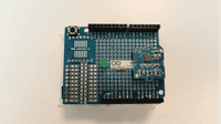
- A Prototyping board. We highly recommend using the Arduino Proto Shield Rev3 (UNO Size) because it will make your life much easier. If you want you can of course use a general prototyping shield but it requires you to do some additional soldering.
- Components that are placed on the shield.
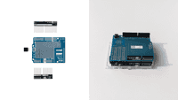
Step 1 Assemble Proto Shield
Once you have gathered all your materials it’s time to start the assembly. The first step is to assemble the Proto Shield and make sure it fits nicely on top of the UNO. If you are new to soldering check out our soldering tutorial here.
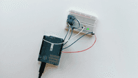
Step 2 Prototype Circuit
Now it’s time to put your components onto your shield. But before you get all excited and start soldering everything onto your shield we highly recommend prototyping and testing your circuit on a breadboard, making sure everything works as expected.
You don’t want to spend a bunch of time soldering everything neatly into place just to realize afterward that you are missing a resistor or something else and then spend even more time desoldering everything again.
Step 3 Solder Components
After you have verified and made sure everything works as you want it’s finally time to solder all components into place. Once done you simply plug in your UNO R4 Minima / UNO R4 WiFi, upload your code, and if everything was done correctly, congratulations you now have built your very own customizable Arduino UNO R4 shield.
If it doesn’t work as expected make sure that everything is soldered properly and nothing is loose. If you have a multimeter laying around use it to check the connections.
Step 4 Document your work
Be sure to document your work both for your own sake as well as for others. Sharing project ideas is an excellent way of learning more about electronics. Project Hub is a great place to document your work and share it with others. See you there!