Bluetooth Controlled RGB LED strip
I am Vishal, I make amazing things on my youtube channel please checkout.
Halloween is about to come and already all are doing their preparations, in my previous project I made an Uncanny eye pendant , Which is already rocking. People really like the pendant because this can be wear on Halloween, as well as on a simple dress.
I made an RGB pumpkin wall light, which can be controlled by a smartphone via Bluetooth, it has different modes and different colors so you can choose the color of the light according to your mode.
There are different types of light lamps available in the market, so following the same theme I made a pumpkin lamp, which can be hung on the wall, it can be used for the light lamps in-room or just hang it an outer wall of your house that will make it scarier for people.
I made it with some Arduino nano, RGB led strip, MOSFETs, and an HC-05. I soldered all of the components on the Zero PCB and powered it with a 12v adapter. Let’s start the project so you can get detailed information.
Quartz components :- A Big thank you to quartz components for sending me stuff for this project, Do check out quartzcomponents.com , to buy components at affordable prices.
The Arduino Nano is a small, complete, and breadboard-friendly board based on the ATmega328. It has the same functionality as the Arduino UNO but in a different package. It lacks only a DC power jack and works with a Mini-B USB cable instead of a standard one.
HC-05 Bluetooth Module is an easy-to-use Bluetooth SPP (Serial Port Protocol) module, designed for a transparent wireless serial connection setup. Its communication is via serial communication which makes an easy way to interface with the controller or PC.
This is a strip with 3 colors LED and some resistor, it can be directly connected with a 12v supply. It comes in two configurations Common cathode and common anode.
Here we make two things, one is the base of the circuit and LED, and the second is the pumpkin.
First of all, we make the base of the circuit and LED, to make this, cut the equal size of strips as shown in the image. You can cut it with a paper cutter or you can use a hot wire to get a perfect cut.
Stick four strips in a squire shape as shown in the image, you can see a piece of small squire at the corner of the big squire it is to support the circuit. This part will hold all LED strips along with the circuit which we will do in the circuit part, for now, let’s build a pumpkin from foam board.
AS you can see in the image, Cut a pumpkin shape out of the foam sheet. As I said cut it with a hot wire or paper cutter. The easiest way to cut it is, draw the pumpkin on the foam sheet and slowly cut the shape.
After cutting the Pumpkin out of the foam board, I found that the light passes through the foam board, so I cut a black sheet same as the foam sheet, and placed it on the foam pumpkin with help of glue.
In the circuit diagram, I used an Arduino nano to make things small, Arduino nano is programmed with several RGB led patterns and colors which can be changed by Bluetooth command, as a Bluetooth we are using an HC05 Bluetooth module, which receives commands from a smartphone.
Arduino nano runs on 5V but the led strip runs on 12v so we need MOSFETs, here we are using IRFZ44n MOSFET, which can be turned on by a 5v signal from Arduino nano and it can drive led trip. I have used three, one for each color.
As given in the Arduino diagram I have used 10, 11 pins as software RX and TX pin to communicate with the HC05 Bluetooth module. Pin 3, 5, 6 is used to control the LED strip color, this pin has PWM so we can control the brightness of each color.
There is a 100E resistor is connected in between gate and Arduino to control the current and a 10K is connected to pull down the floating gate.
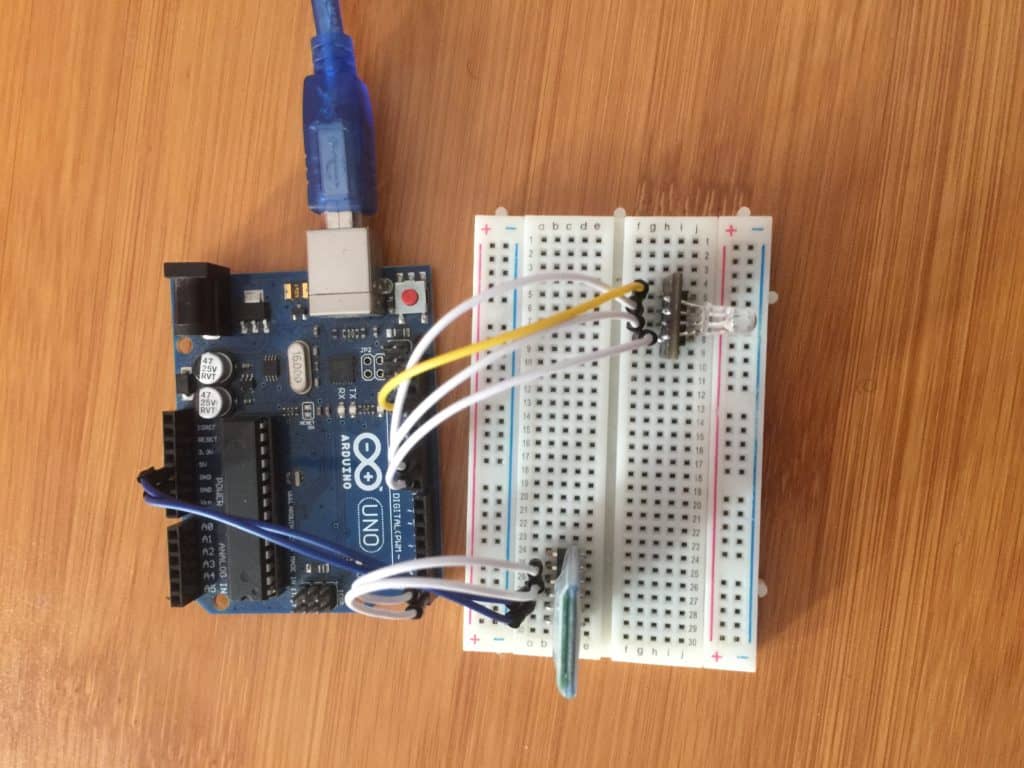
First of all, I have connected all the circuits on the breadboard to test all things are working properly or not, then I have connected it on zero PCB.
After connecting the circuit, upload the code in Arduino, you can download the code from my Github page .
For testing purposes, I am using Arduino UNO, when you power the Arduino it starts the led will fade in random colors, to control the led you have to connect with the app.
To Connect the lamp with the smartphone, first of all, download it from my GitHub page or from the play store both links are given below.
Till the app is installing, turn on the device we made, and turn on Bluetooth in the smartphone. Search for a new Bluetooth device and you will find HC05 as a new Bluetooth. Paire it with password ”1234” or “0000”.
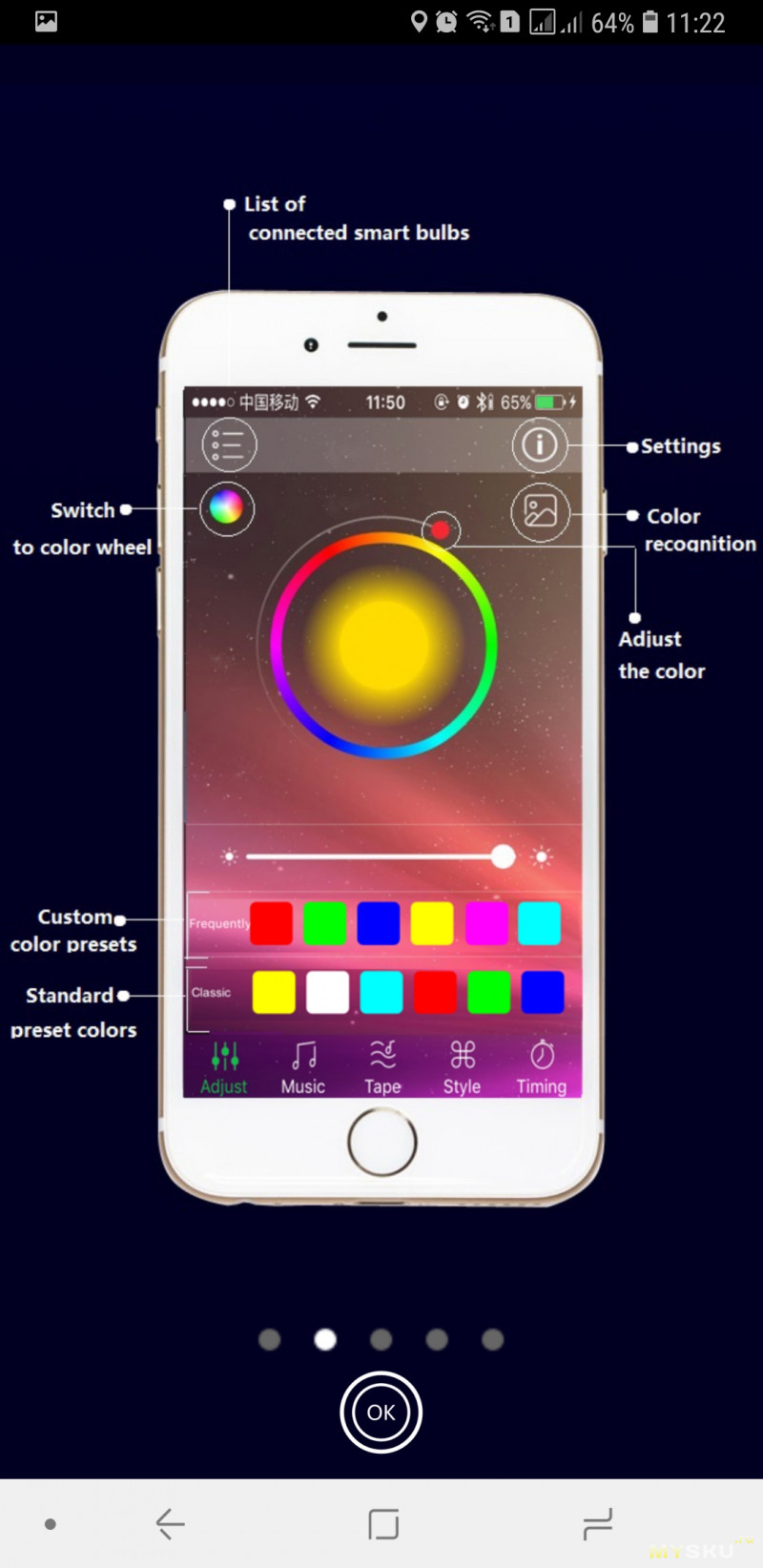
Now open the app and click on pair, after clicking on pair click on HC05, and once you see the “connected” name your app is ready to control the lights.
Once everything is done stick the led strip on the squire base, which we made from foam board. You can see there is a circuit on the corner.
Stick it on the wall with help of some double-sided tape, you can use nails if you want. Now place our pumpkin head on the base.
I have added some cotton to it to diffuse the light inside the pumpkin and white cotton looks good on it.
Now everything is done just choose the color and pattern of your LED, and you are ready to boom. It looks awesome in light.
Bluetooth RGB контроллер и его возможности
Почему именно блютуз контроллер? Самым очевидным преимуществом Bluetooth является то, что ему не требуется пульт. Вместо него вы сможете использовать приложение на смартфоне. В современном доме и без того много техники, управляемой пультами. Если добавить к ним еще один, а то и несколько, не запутаться будет просто невозможно.
Недавно в нашем интернет-магазине появилась новинка: bluetooth RGB контроллер. Сегодня мы бы хотели презентовать этот товар и рассказать вам о тех возможностях, которые предоставляет это устройство.
Начнем издалека: почему именно блютуз контроллер? Самым очевидным преимуществом Bluetooth является то, что ему не требуется пульт. Вместо него вы сможете использовать приложение на смартфоне. В современном доме и без того много техники, управляемой пультами. Если добавить к ним еще один, а то и несколько, не запутаться будет просто невозможно.
Кроме того, пульты от RGB ленты компактны и их легко потерять. Если учитывать, что отдельно они не продаются, такая потеря приведет к необходимости покупать новый контроллер. В отличие от них, ваш смартфон почти всегда под рукой. В крайнем случае, если вы забудете куда его положили, вы сможете просто попросить кого-нибудь вам позвонить. В случае с обычным RGB пультом, так просто вы его не найдете.
Наконец, RGB пульт требует батареек для работы. Этот небольшой на первый взгляд минус может вырасти в проблему, если ваш контроллер «зашит» в потолок, на улице ночь, а батарейки от пульта внезапно сели.
Основные функции RGB блютуз контроллера:

Кроме этих очевидных и привычных для каждого контроллера функций, bluetooth контроллер обладает некоторыми особыми возможностями, недоступными обычным контроллерам. Например:

- Работа по расписанию. Например, включение утром по будням на два часа, когда вы собираетесь на работу и вечером, в то время, когда вы приходите домой.
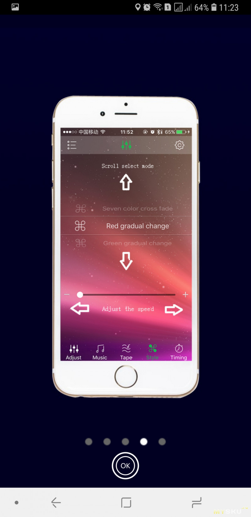
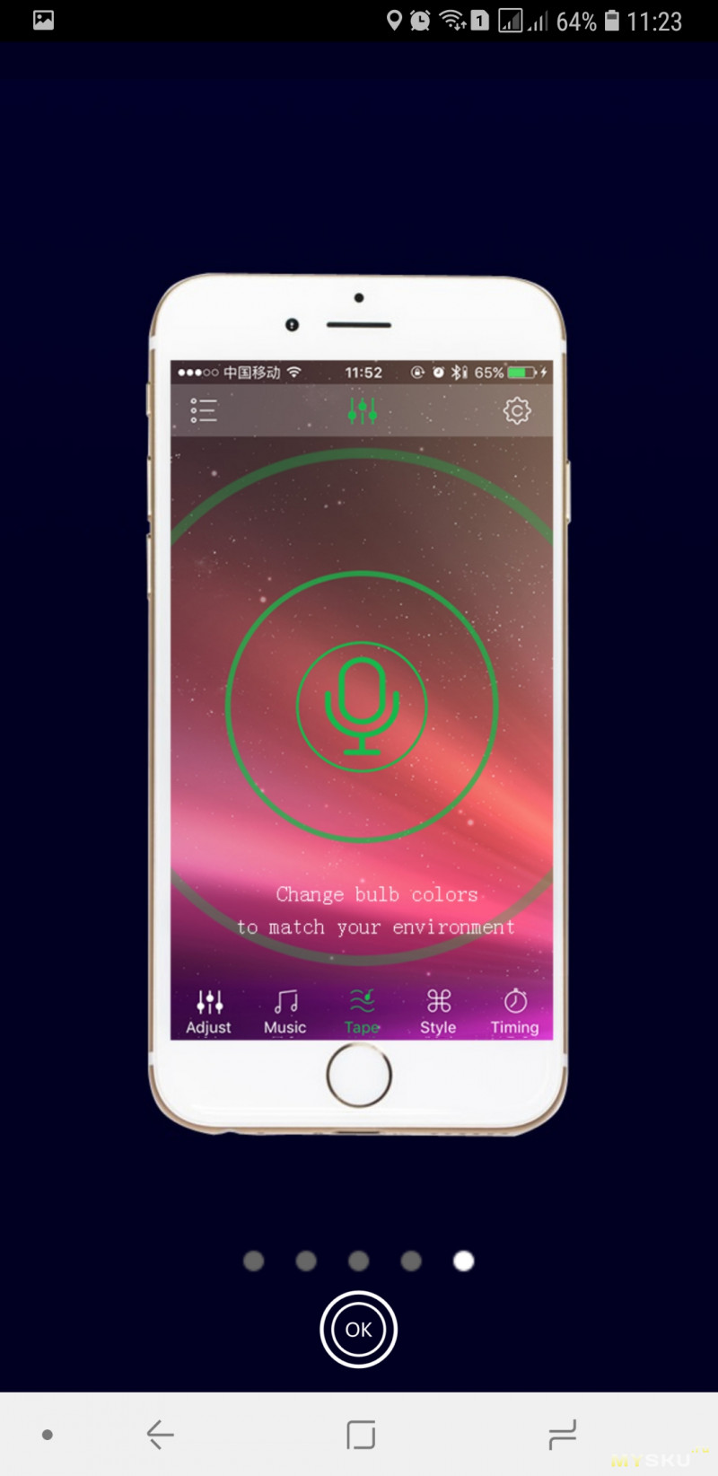
- Улавливание звуков. Лента будет реагировать на звуки, хлопки, разговоры, пение. Улавливает не только громкость но и тональность звука.
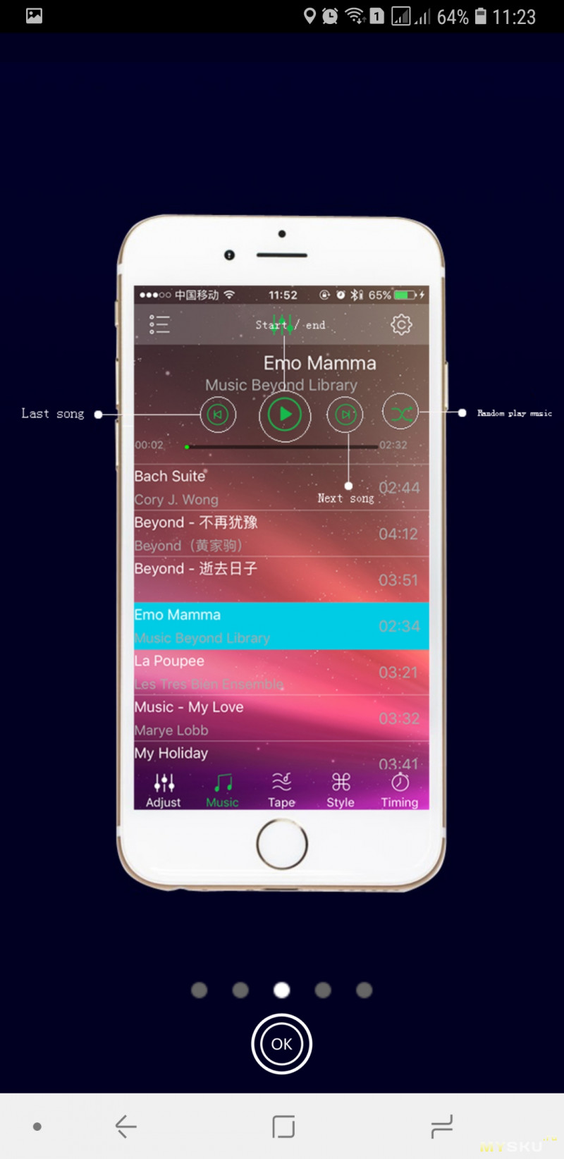
- Музыкальный режим. В этом режиме контроллер регулирует яркость и цвет ленты в такт музыке.

Раздельное управление несколькими контроллерами, или их группировка с помощью одного смартфона.
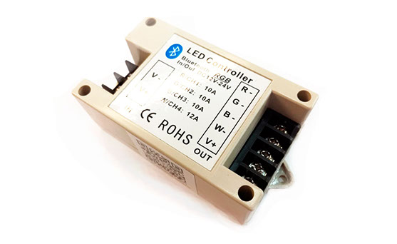
Как видите, есть ряд интересных функций, доступ к которым открывают нам Bluetooth контроллеры. Наша модель является пятиконтактной, т.е. может быть использована как с обычной лентой, так и с RGB+W моделью. Вы также можете установить RGB и просто белую ленту в два ряда и управлять всем с помощью этого контроллера. Это будет не менее удобно, зато гораздо дешевле, чем ставить RGB+W ленту. Если у вы хотите почитать технические характеристики или купить блютуз контроллер, вы можете сделать это здесь.
Если у вас уже есть bluetooth контроллер, скачать драйвер для управления вы можете здесь:
Android
IOS
Команда Giant4.ru
Контроллер RGBW LED ленты: очередная лажа
Я уже рассказывал про RGBW светодиодную ленту в одном из своих обзоров, теперь пришло время рассмотреть и контроллеры для них. В этом посте – контроллер с Bluetooth. Расчленёнка внутри.
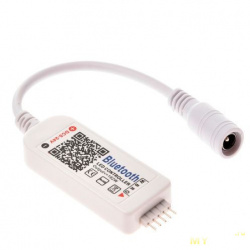
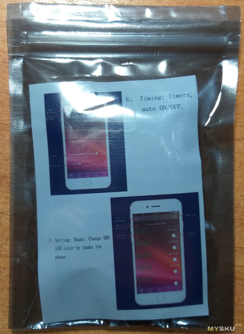
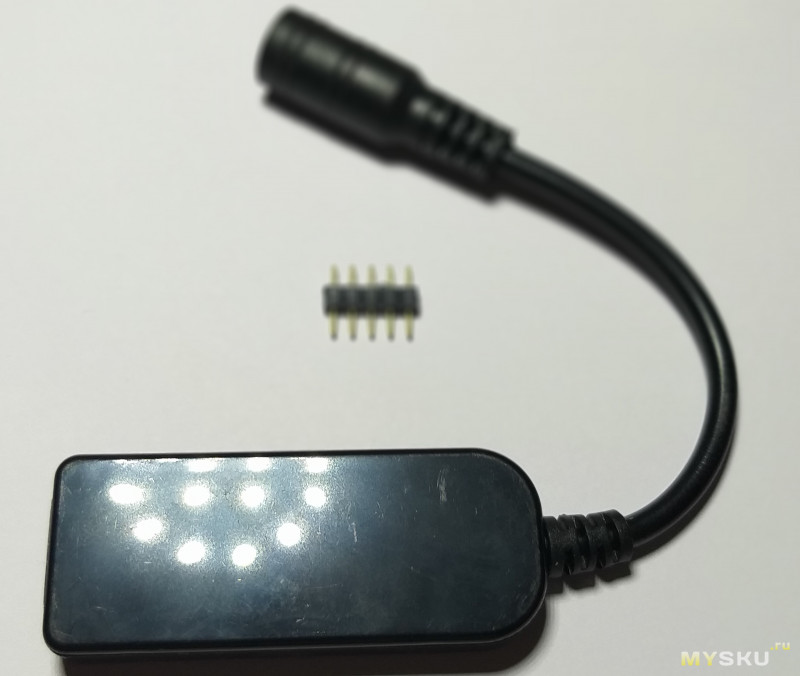
Поставляется контроллер в антистатическом пакете чуть больше него самого по размеру. Кроме устройства в комплекте только гребенка 5×1 с шагом между контактами 2 мм. для подключения ленты, и инструкция с QR кодом для скачивания приложения. 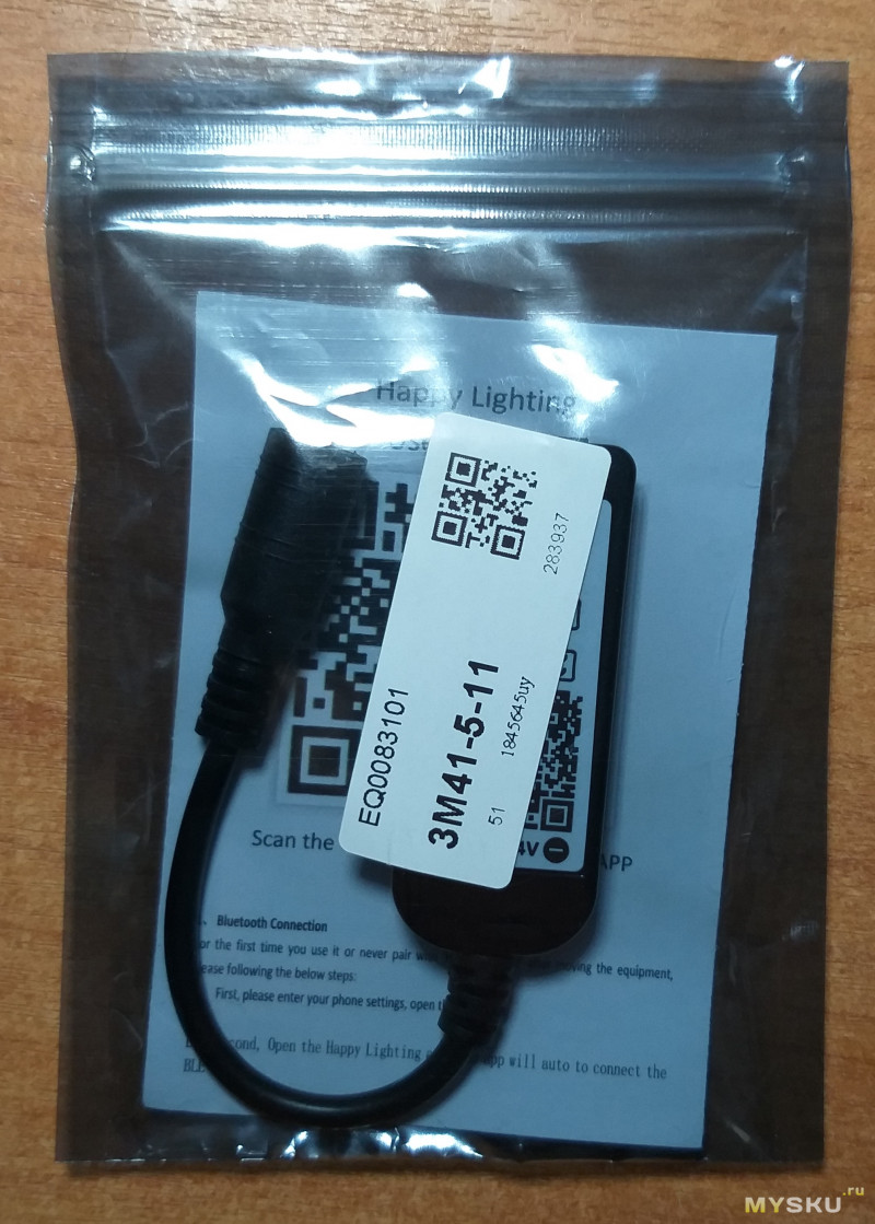
Напряжение питания составляет от 5 до 24 В.
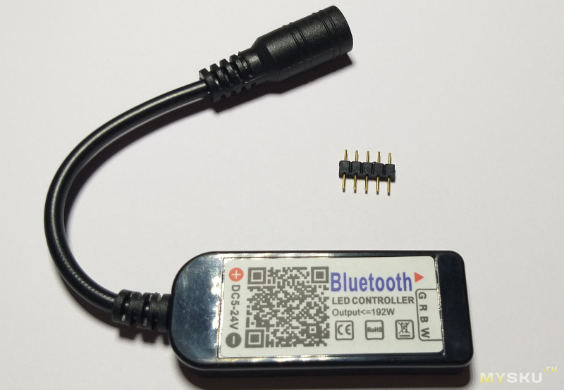
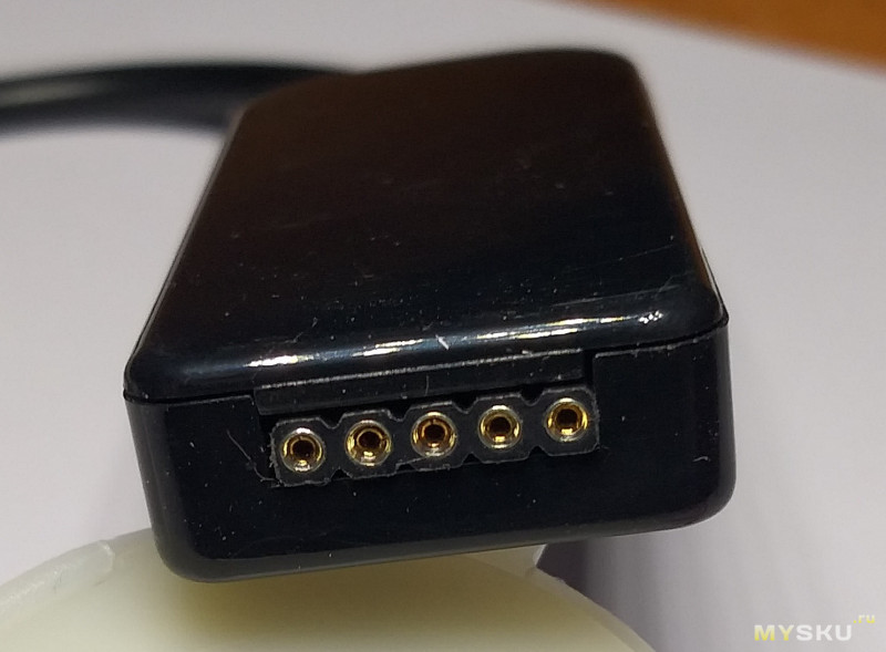
Устройство ничем не примечательно, из корпуса выглядывает только «хвост» с гнездом 5,5×2,1 мм. для подключения блока питания.
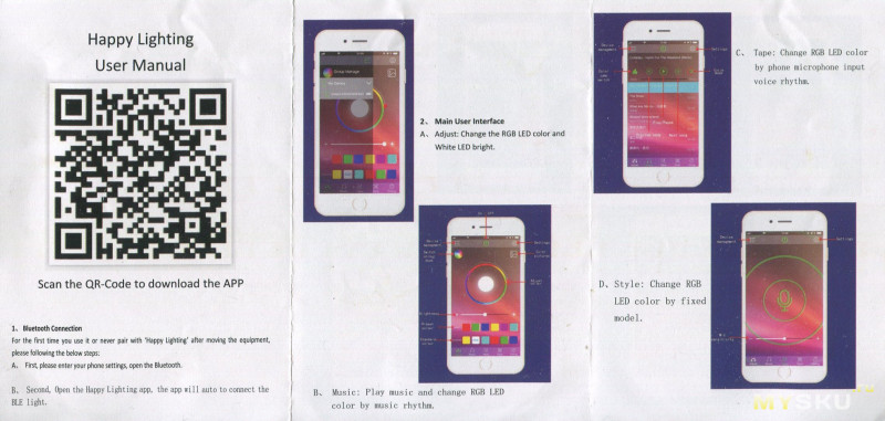
Подключение более чем незамысловатое – скачиваем приложение «Happy Lighting», включаем Bluetooth, и подключаемся к устройству. Все, можно работать! И ничего не работает.
Я скачивал приложение на следующие телефоны:
1) Samsung Galaxy A6+;
2) Samsung Galaxy Grand Prime;
3) LG G4s.
Поэтому вывод простой, дело не в телефоне (-ах), а в самом приложении.

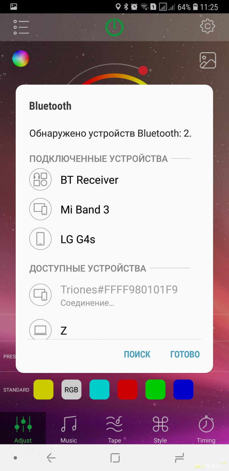
Похоже, приложение настолько кривое, что (судя по отзывам) у десятков людей, купивших контроллер, ничего не работает.
Тогда вскрываем?
Вот и обещанная расчлененка: 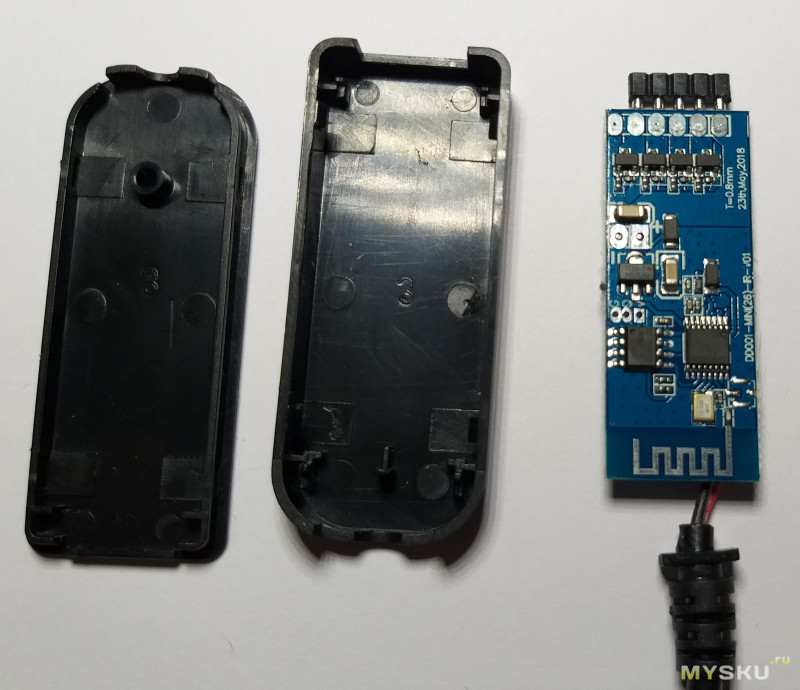
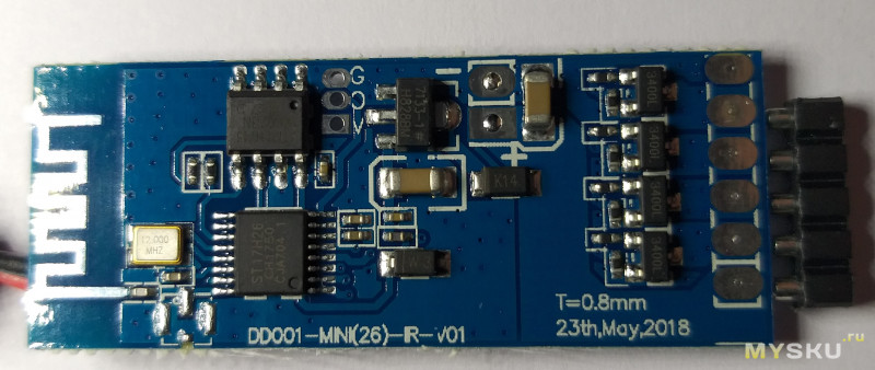

Рулит всем небезызвестный контроллер ST17H26ES16 китайской компании Lenze Technology, про который я рассказывал в одном из прошлых обзоров. Кстати, с устройством из того обзора тоже были косяки. Совпадение?
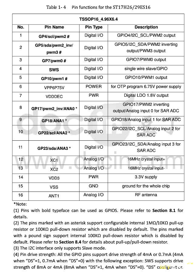
Еще раз приведу распиновку микросхемы: 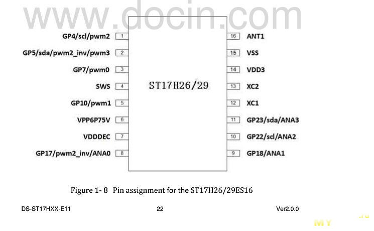
Помимо нее на борту стоит ATtiny45 и линейный стабилизатор HT7133-1 и 4 ключа 3400L.
Судя по плате, изготовлена она 28 мая 2018. Монтаж компонентов производился машиной, претензий к нему нет. Следы неотмытого флюса обнаружены только на проводах питания и у гребенки для подключения ленты.
Естественно, был открыт спор, который я выиграл.
Товар не работает, к покупке не рекомендуется.
Arduino Bluetooth RGB led control using Android app
RGB LEDs play a large part in applications like outdoor decoration lighting in cities, stage lighting designs, home decoration lighting and LED display matrix. Recently, RGB color mixing technology can also be found in LCD backlighting and projectors.
In this tutorial we will learn how the RGB LED works and how we can control RGB led using HC-05 Bluetooth module, Arduino IDE and an Android application.
Before proceeding, you can make reference from my other tutorial on how to use the HC-05 Bluetooth module with Arduino from the link below;
What is RGB LED?
RGB LED is actually three LEDs, red, green, and blue inside one package. Three PWM Outputs are used to control the RGB LED. A PWM value of 0.0 would be off and a 1.0 full on for each color LED. This allows a program to vary both the color and brightness level of the LED.
Typically an RGB LED has four pins. One common pin and one for each of the three LEDs. In the LED seen below, the common pin is the longest pin. The RGB LED can be classified as either common anode or common cathode. The common pin in the common anode RGB LED is connected to VCC while in the common cathode it is connected to the ground.
NOTE: Red, Green and Blue are called primary colors and by mixing each other with different intensity we may get millions of color outcomes. This is the basic concept of the RGB led.
Connecting the RGB LED and HC-05 Bluetooth module to Arduino
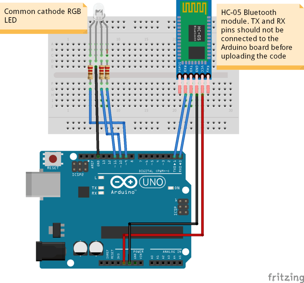
- VCC – to VCC of Arduino.
- GND – to GND of Arduino.
- RX – to digital pin 0(TX pin) of Arduino.
- TX – to digital pin 1(RX pin) of Arduino.
Note:
i).Connect RX and TX pins after uploading the code
ii).The terminals of the RGB LED should be connected to PWM pins of the Arduino.
CODE
This code is mainly for changing the PWM for simulating analog output which will provide different voltage levels to the LEDs so we can get the desired colors. These values can vary from 0 to 255 which represents 100 % duty cycle of the PWM signal or maximum LED brightness.
The RGB led will give the color corresponding to the value determined by the color wheel of the Android application.
#include #include SoftwareSerial mySerial(0,1); // RX and TX pins int PIN_RED = 9; int PIN_GREEN = 10; int PIN_BLUE = 11; String RGB = ""; String RGB_Previous = "255.255.255"; String ON = "ON"; String OFF = "OFF"; boolean RGB_Completed = false; void setup() < pinMode (PIN_RED, OUTPUT); pinMode (PIN_GREEN, OUTPUT); pinMode (PIN_BLUE, OUTPUT); Serial.begin(9600); mySerial.begin(9600); RGB.reserve(30); >void loop() < while(mySerial.available()) < char ReadChar = (char)mySerial.read(); if(ReadChar == ')') < RGB_Completed = true; >else < RGB += ReadChar; >> if(RGB_Completed) < Serial.print("RGB:"); Serial.print(RGB); Serial.print(" PreRGB:"); Serial.println(RGB_Previous); if(RGB==ON) < RGB = RGB_Previous; Light_RGB_LED(); >else if(RGB==OFF) < RGB = "0.0.0"; Light_RGB_LED(); >else < Light_RGB_LED(); RGB_Previous = RGB; >RGB = ""; RGB_Completed = false; > > void Light_RGB_LED() < int SP1 = RGB.indexOf(' '); int SP2 = RGB.indexOf(' ', SP1+1); int SP3 = RGB.indexOf(' ', SP2+1); String R = RGB.substring(0, SP1); String G = RGB.substring(SP1+1, SP2); String B = RGB.substring(SP2+1, SP3); Serial.print("R="); Serial.println( constrain(R.toInt(),0,255)); Serial.print("G="); Serial.println(constrain(G.toInt(),0,255)); Serial.print("B="); Serial.println( constrain(B.toInt(),0,255)); analogWrite(PIN_RED, (R.toInt()));//comment if colors are inverted analogWrite(PIN_GREEN, (G.toInt()));//and uncomment part below. analogWrite(PIN_BLUE, (B.toInt())); // analogWrite(PIN_RED, (255-R.toInt()));//uncomment if colors are inverted // analogWrite(PIN_GREEN, (255-G.toInt()));//and comment above part. // analogWrite(PIN_BLUE, (255-B.toInt())); >