- Ugoos Remote Pairing & Calibration
- Bluetooth remote control power
- Arduino Powered Bluetooth Remote Relay Switch
- Introduction: Arduino Powered Bluetooth Remote Relay Switch
- Step 1: Connecting the Arduino Board to the Computer
- Step 2: Arduino Sketch
- Step 3: Uploading the Code
- Step 4: Wiring It All Together.
- Step 5: Connecting to Your Phone and Testing
- Step 6: Fitting Everthing in the Box
- 1 Person Made This Project!
- Recommendations
- Wear It Contest
- Unusual Uses Contest
- Metal Contest
- 22 Comments
Ugoos Remote Pairing & Calibration
Ugoos remote control is a brand-new Bluetooth accessory for any android device, not only Ugoos but any TV Box on the market. The first time appeared as a standard accessory for main Ugoos devices and now also available for separate purchase.
Here is example how does Ugoos AM7 work with it as a standard remote, so it is possible to use both bluetooth an IR functionality.
Ugoos devices have a simple wizard, which is start from the very first time when TV Box powered:
Ugoos Remote can be used for any TV Box or other android device. Hold «Volume +» and «Volume -» buttons in order to set the remote into pairing mode.
You will need to just connect Remote as a standard Bluetooth control device in accessories settings.
Ugoos Remote also has IR learning button function.
This function available only for right side “Power” button. Simple actions should be provided
- After the Ugoos remote control powered on, press and hold the “Power” button for about 3 seconds, then release the finger after the red light keeps on, and then it enters learning status.
- Hold the remote control to be learned, point it at this remote control with a distance about 3-5 cm, then press needed button to be learned.
- After the learning is successful, the red light flashes twice and then go out to indicate success. Note that the Ugoos remote will automatically exit learning state after about 10 seconds.
Ugoos Remote Calibration
For Ugoos remote calibration you need:
-> Hold “OK” and “Home Button” until light indicator turns on
-> Place remote on the plain surface and wait until the indicator turns off
Bluetooth remote control power

Rather than buying something, make it.
Browse thousands of projects created by the Arduino community
794805 views • 605 comments • 415 respects
Arduino Based Mini CNC 2D Plotter
165598 views • 40 comments • 214 respects
212818 views • 90 comments • 57 respects
Ultrasonic Security System
163029 views • 142 comments • 188 respects
157244 views • 63 comments • 60 respects
Measure Heart Rate and SpO2 with MAX30102
321871 views • 154 comments • 244 respects
Share and Compete in Project of the Month!
Unlock amazing rewards by submitting your project today.
Create projects fast, with no coding
Import, use and customize ready-made templates for your IoT projects
Dream big, we will take care of the rest
See what you can create with Arduino Cloud
White Mountains Regional High School
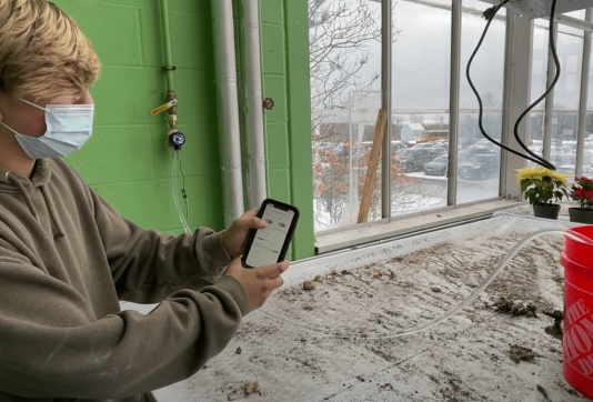
Discover how this school is working with remote sensing applications that allow them to do things like automate lighting, regulate temperature, adjust humidity, and check on the greenhouse from their phones.
Smart ovens take a leap into the future
How a strong partnership and the Arduino Portenta Machine Control led historical company Rinaldi Superforni to revolutionize their business
The new Portenta X8 and Max Carrier
Industrial Arduino and Linux combined to get the best of both worlds
Arduino Powered Bluetooth Remote Relay Switch
Introduction: Arduino Powered Bluetooth Remote Relay Switch
I wanted to build a simple 2 channel bluetooth remote switch box.
to allow me to remotely switch various devices on and off from my android phone.
The device had to be small easy to use and flexable enough to control anything I wanted.
some of the uses are controling my slr camera. and to switch on mains devices like lights.
parts needed.
1 arduino board ( i used a arduino nano as it was small and easy to attach to a computer to program)
1 relay board
1 bluetooth module (I used a jy-mcu module because it was cheap)
A plastic box to put everything in
A battery holder
I purchased the arduino board the bluetooth module and the relay board from ebay.
the plastic box and battery holder came from maplin.
be careful when purchasing the bluetooth module and check that its the board and bluetooth chip. as some on ebay are just the board without the bluetooth chip.
Step 1: Connecting the Arduino Board to the Computer
first of all I connected the arduino board to my computer usb port.
the board should light up.
now if you havnt got the arduino IDE software you should go here http://arduino.cc/en/Main/Softwareto download it
it should already be in the repositorys if you are using ubuntu linux.
when the software has been installed and opened. check the port and board setting are correct.
this will be under tools > board (select the board option to match your arduino board)
and tools > serial port. if this is greyed out you will have to check that your drivers are installed correctly for your board.
when the software is set up and communicating with your arduino. its time to write the code.
Step 2: Arduino Sketch
here is a copy of my arduino sketch.
what will happen is when I send a command A to H the relay will be switched on and if I send a to h the relay will be switched off.
I have programmed it so that
A is relay one on (latched)
B is relay two on (latched)
C is relay one on for 1 second
D is relay two on for 1 second
E is relay one on for 5 second
F is relay two on for 5 seconds
G is relay one on for 1 second then relay two on then both off
H will switch relay one on and off for 1000 times
the relays switch on when the digital pin is grounded. and the relay switches off when the digital pin goes high
char val; // variable to receive data from the serial port
int ledpin = 2; // LED connected to pin 2 (on-board LED)
void setup()
pinMode(ledpin = 2, OUTPUT); // pin 2 (on-board LED) as OUTPUT
pinMode(ledpin = 3, OUTPUT); // pin 3 (on-board LED) as OUTPUT
Serial.begin(9600); // start serial communication at 115200bps
if( Serial.available() ) // if data is available to read
;
>
val = Serial.read(); // read it and store it in ‘val’
if( val == ‘a’ ) // if ‘a’ was received led 2 is switched off
digitalWrite(ledpin = 2, HIGH); // turn Off pin 2
>
if( val == ‘A’ ) // if ‘A’ was received led 2 on
digitalWrite(ledpin = 2, LOW); // turn ON pin 2
>
if( val == ‘b’ ) // if ‘b’ was received led 3 is switched off
digitalWrite(ledpin = 3, HIGH); // turn Off pin 3
>
if( val == ‘B’ ) // if ‘B’ was received led 3 on
digitalWrite(ledpin = 3, LOW); // turn ON pin 3
> //else (ledpin = 3, LOW) //set led pin 3 to low state
if( val == ‘C’ ) // if ‘C’ was received led 2 on for 1 second
digitalWrite(ledpin = 2, LOW); // turn ON pin 2
delay(1000); // wait 1 second
digitalWrite(ledpin, HIGH); // turn Off pin 2
>
if( val == ‘D’ ) // if ‘D’ was received led 3 on for 1 second
digitalWrite(ledpin = 3, LOW); // turn ON pin 3
delay(1000); // wait 1 second
digitalWrite(ledpin, HIGH); // turn Off pin 3
>
if( val == ‘E’ ) // if ‘E’ was received led 2 on for 5 seconds
digitalWrite(ledpin = 2, LOW); // turn ON pin 2
delay(5000); // wait 500 milli seconds
digitalWrite(ledpin, HIGH); // turn Off pin 2
>
if( val == ‘F’ ) // if ‘F’ was received led 3 on for 5 seconds
digitalWrite(ledpin = 3, LOW); // turn ON pin 3
delay(5000); // wait 500 milli seconds
digitalWrite(ledpin, HIGH); // turn Off pin 3
>
if( val == ‘G’ ) // if ‘G’ was received turn led pin 2 on for 500ms then switch off and turn on pin 3 for 500 mili seconds then off
digitalWrite(ledpin = 2, LOW); // turn ON pin 2
delay(500); // wait 500mili second
digitalWrite(ledpin, HIGH); // turn Off pin 2
digitalWrite(ledpin = 3, LOW); // turn ON pin 2
delay(500); // wait 500 mili second
digitalWrite(ledpin, HIGH); // turn Off pin 2
>
if( val == ‘h’ ) // if ‘h’ was received switch off all pins
digitalWrite(ledpin = 13, LOW); // turn Off pin 13
digitalWrite(ledpin = 2, HIGH); // turn Off pin 2
digitalWrite(ledpin = 3, HIGH); // turn Off pin 3
>
if( val == ‘H’ ) // if ‘H’ was received switch pin 2 on and off 1000 times
for(int i = 0; i < 1000; i++)
digitalWrite(ledpin = 2, HIGH); // turn ON pin 2
delay (1000); //wait 1000 mili seconds
digitalWrite(ledpin = 2, LOW); // turn Off pin 2
delay (1000); //wait 1000 mili seconds
Step 3: Uploading the Code
when you are happy with the sketch it can be uploaded to the arduino by pressing the upload button in the IDE.
you will not be able to upload the code if the bluetooth module is already connected to the arduino.
Step 4: Wiring It All Together.
the relay board and arduino will need a 5volt power supply.
the bluetooth module can be powered from the 3.3 volt pin on the arduino.
the tx on the bluetooth board will be connected to the rx pin on the arduino
the rx pin on the bluetooth board will be connected to the tx pin on the arduino
and the digital output pins 2 and 3 on the arduino will be wired to the relay board as shown in the diagram.
Step 5: Connecting to Your Phone and Testing
now if you have uploaded the code ok.
and everything is wired correctly the boards should power on and the light on the bluetooth module should flash.
I wanted to be able to control it from my android phone.
luckly for me Amphan had already done all the hard work and writen a very good android app called Arduino Bluetooth Control. which is on the google play store
https://play.google.com/store/apps/details?id=com.app.control&hl=en
after installing and opening the arduino bluetooth control app. I had to pair the phone to the bluetooth module.
my module was listed as HC-06 and the pin was 1234.
after pairing it was just a matter of pressing the connect button on the bottom of the app.
they connected ok and I was able to switch the relays on and off using the buttons on the app.
if you have problems connecting or controlling the arduino check that the baud rate in the software matches the baud rate of the bluetooth module.
Step 6: Fitting Everthing in the Box
the next step was to mount everthing in a plastic box.
the box i got from maplin was quite small and the battery holder just fitted after a little alteration.
I had to cut a few holes and drill some mounting holes for the relay board.
and here is the finished device.
after checking that it all still worked propperly.
I wired up a light to the relay to check that it all switched as required.
1 Person Made This Project!
Did you make this project? Share it with us!
Recommendations
Wear It Contest
Unusual Uses Contest
Metal Contest

22 Comments
you are using 6 volts there not 5.
is the relay module ok with that?
Nice tutorial thank you,but code working two relays only please send me multiple relay control code for ardunio bluetooth control. im confusing coding multiple relays like 12ch or 8ch relay
mail id: thunaivelan92@gmail.com
Sir my system doesn’t wrk properly code and connection successfully done but device not wrk Bluetooth control
can i control bluetooth module through my system
dear simon72post i am building bluetooth remote relay switch same as yours. i am using components as mention below
2) 4 channel, 12vdc relay card.
4) Arduino bluetooth control device android app
How i wired my componnents i have shown in blow pic.
now please can you provide me a sketch so that i can operate relay via my android mobile using Arduino bluetooth control device android app.
i think u understand what i want from you i am a bignner in this arduino world and i found your this post very much closer to my need
and please guied me my friend
please my friend help me you can mail me on sharmaz747@gmail.com
please send the skecth to my email ilhambintang559@gmail.com
I have a questiin you may can help with i do heating and air have a unit that has bad tstat wire going from indoor to outdoor unit so it wont allow anything outside to kick on and cant run new wire its not possible is there any bluetooth relay i can build so when thermostat calls for ac it will send signal to od unit and close a relay to allow 24 volts to contator i can put a transformer out there to. Make the 24v but having trouble finding away to control it
i have made this and followed all the instructions,but when i connect by arduino power ,the relays are switching on,my phone connected to bluetooth device but unable to control the relays,they are continously switched on
how many days this project would run if i operate it whole day ?
I have a problem, when I press the button on my android device sometimes the relay doesn’t respond. but I can see TX and RX LED on my arduino blinking.
Great and thanks it worked for me on 4 relays
how can 4 relay, how improve its


