- Как из камеры ноутбука сделать беспроводную wifi камеру для смартфона
- Понадобится
- Как сделать беспроводную wi-fi видеокамеру
- Смотрите видео
- Arduino Bluetooth Camera
- Step 1: List of Components Needed
- Hardware:
- Software:
- Step 2: Preparing
- Software
- Android
- Bluetooth module
- Attachments
- DIY Low-Cost Bluetooth Camera Light
- Supplies
- Step 1: Planning and Designing
- Attachments
- Step 2: Ordering and Assembling
- Step 3: Programming and Testing
- Attachments
- Step 4: Housing
- Attachments
- Step 5: Android App
- Attachments
- Be the First to Share
Как из камеры ноутбука сделать беспроводную wifi камеру для смартфона
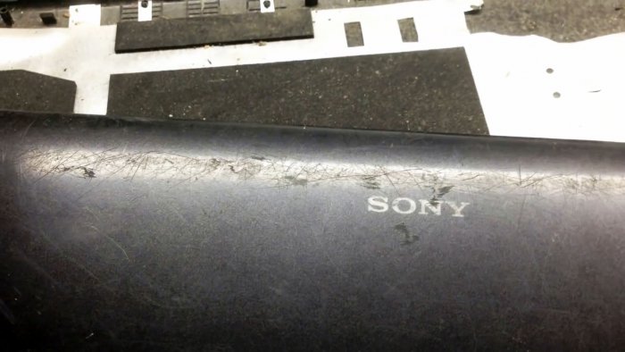
Это самоделка из разряда: «что еще можно сделать из деталей сломанного ноутбука?» В ноутбуке по сути много полезных вещей для самоделок. В данном мастер-классе будем использовать его камеру. Сделаем ее беспроводной, чтобы можно было смотреть в нее через любой смартфон на расстоянии до 50 метров.
Понадобится
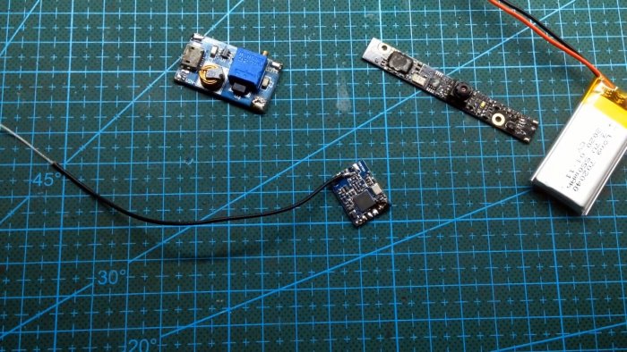
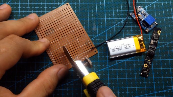
- Wi-fi модуль — http://ali.pub/5h3v69
- Повышающий преобразователь — http://ali.pub/5h3v8e
- Литий-ионный аккумулятор 3,7 В 550 ма/ч — http://ali.pub/5h3vb4
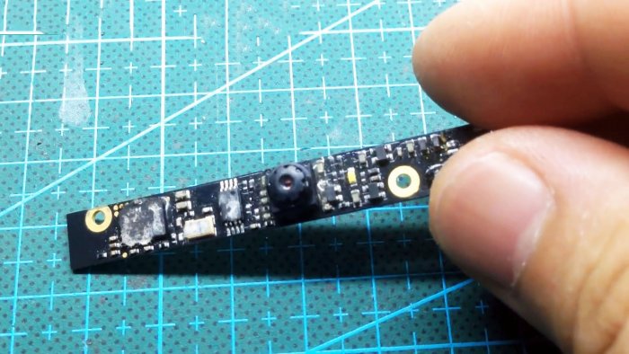
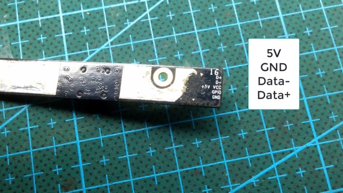
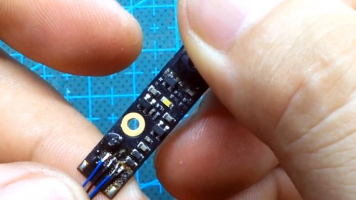
- Видеокамера от ноутбука или нетбука.
Как сделать беспроводную wi-fi видеокамеру
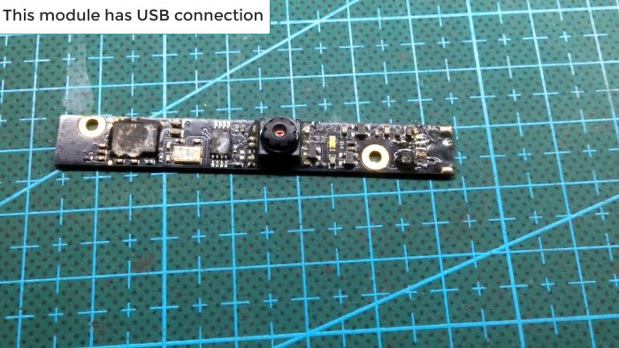
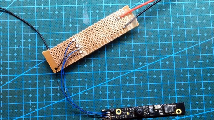
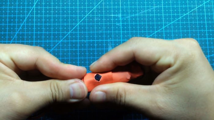
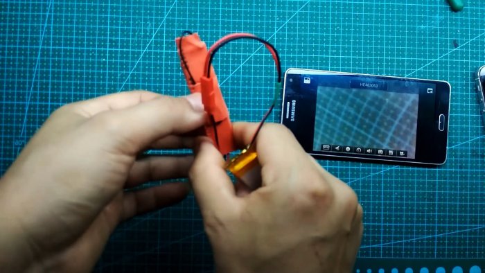
По сути это обычная веб-камера с USB интерфейсом. Поэтому ее уже можно использовать без переделки: достаточно подпаять провод с разъемом и воткнуть в USB гнездо.
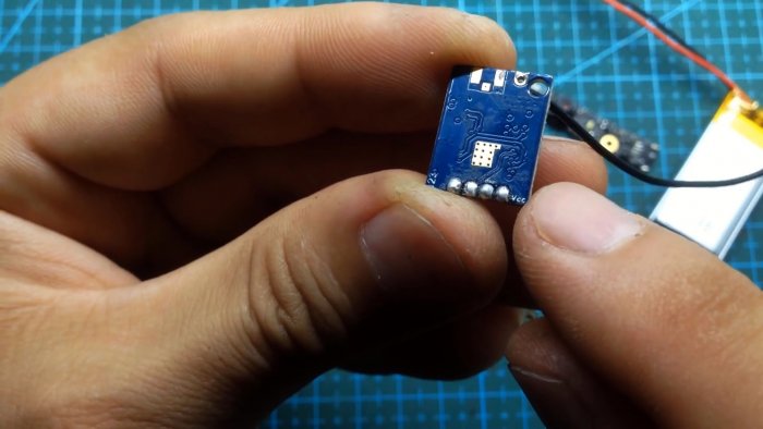
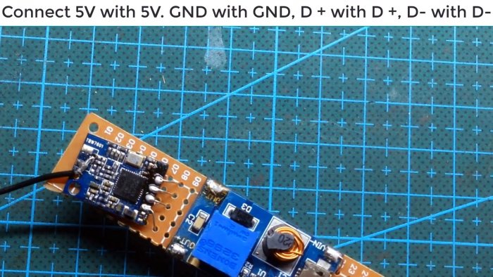
Берем wifi модуль. Он так же имеет интерфейс USB. Это так же готовое устройство, которое используется как wifi адаптер.
Припаиваем к плате преобразователь. К нему через разъем подключаем аккумулятор. Теперь система питания готова. Камера и адаптер будут питаться от напряжения 5 В.
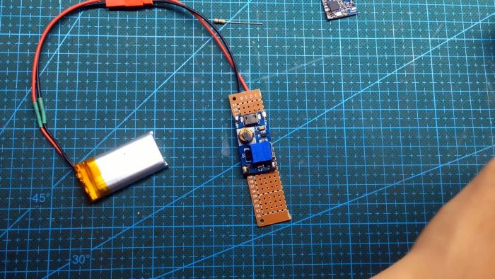
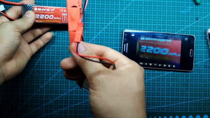
На выход преобразователя подключаем мультиметр, и вращением переменного резистора на плате преобразователя добиваемся выходного напряжения на нем 5 Вольт.
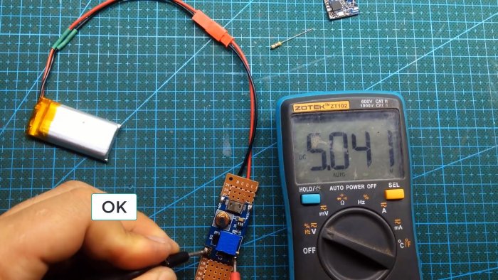
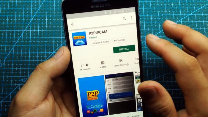
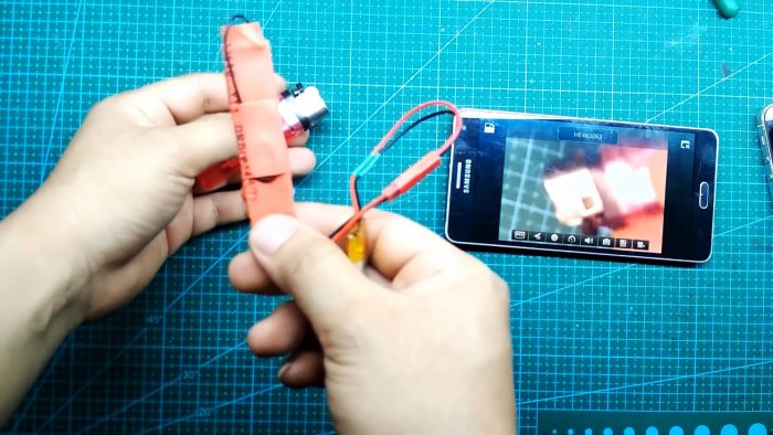
На этом беспроводная wifi камера готова. Подключим к ней питание от аккумулятора. На «Google Play» скачаем любое приложение «P2P Camera» и установим его.
Смотрите видео

- Информация предоставлена исключительно для ознакомления.
- Данное устройство нельзя использовать для наблюдения за лицами без их на то согласия.
Arduino Bluetooth Camera


Today you can hardly surprise anyone with a mobile phone with a camera, wireless gadgets and other technical advances. Thanks to the Arduino platform, millions of people have discovered the wonderful world of electronics and programming. 100,500 instructions were written on how to exchange data between a mobile phone and Arduino via bluetooth . What am I talking about? Yes. I want to exchange data between a mobile phone on Android and Arduino UNO through bluetooth in 100,501 times. But I want to transmit not just a set of characters and numbers, but pictures.
Someone will say that this is impossible, Arduino is too slow to process large amounts of data with good speed. And he will be absolutely right. And what if a little bit of help Arduino — to transfer all the «hard» work on the shoulders of other device? And there is such a device!
This is a unique TFT shield for Arduino. Information about this logo is in these articles: article 1, article 2. In this instructables, I will demonstrate how you can connect via bluetooth between Arduino and Android phone, get a picture from the OV7670 camera on Arduino UNO and transfer it to Android phone. Then, on the contrary, transfer the picture (image from the camera) from the Android phone to Arduino UNO and display it on the screen of a unique TFT shield.
A special application was written for the Android phone.
Brief characteristics of TFT shield:
- Size 3.5 » diagonal,
- Resolution 320×240,
- Number of colors 65536 (16-bit),
- Resistive touch screen (XPT2046 controller),
- 5 buttons,
- RTC IC DS1307 with 3V lithium battery CR1220,
- Slot for connecting a micro SD card,
- 4-pin (2.54 mm) connector for connecting the Bluetooth module HC-05 (-06), ESP8286 WiFi module.
- 20-pin (2.54 mm) connector for camera (OV7670).
Step 1: List of Components Needed
Hardware:
- Arduino UNO;
- Unique TFT shield;
- AC-DC power adapter 6-12 volt, >600mA;
- Camera OV7670;
- Bluetooth module HC-06 (HC-05);
- Android phone.
Attention: It is necessary (!) To use a 6-12 volt power adapter to operate the TFT shield, because the maximum current of 500 mA from USB is not enough for normal operation.
Software:
Step 2: Preparing
Software
All demonstration sketches are written in the Arduino IDE environment, therefore at the beginning it is necessary to install the Arduino IDE — https://www.arduino.cc/en/main/software.
Then you need to install a library for TFT shield — github.com/YATFT/YATFT (download the library and unpack it into the «libraries» folder in the Arduino IDE directory).
After installing the Arduino IDE, you must program the Arduino UNO board. For simplicity, I recommend flashing it separately, without TFT shield. For this:
- Connect the USB cable to the Arduino UNO board;
- Run the Arduino IDE on the computer;
- Select the corresponding port to which the Arduino UNO is connected;
- Download the ArduinoBluetoothCamera.ino demo sketch (and file ov7670_regs.h for camera init);
- Click the button Upload.
If the Arduino UNO board is successfully programmed, you can proceed to the next step.
Android
On the Android phone, you need to install the ArduinoTFT.apk. Allow the app to use the Bluetooth and Camera.
Update 07/25/2020 (Thanks to fano13250)
Hi, i had the same problem with the Android App wich doesn’t work.
Solved after authorized the App to access at the smartphone camera. That’s it. Bye
Bluetooth module
It is necessary to set the exchange rate in the Bluetooth module to be 115200 (command «AT+UART=115200,0,0»). This is the optimal speed at which Arduino UNO manages to receive and process data. (Theoretically, you can increase the speed, optimize data reception and processing, but this requires a larger amount of RAM).
More detailed instructions on how to set the exchange rate can be found on the Internet, for example, here: https://www.instructables.com/id/Communication-Bluetooth-Module-With-HC-05-HC-06/ .
(!) Please note that the Bluetooth module connects to the debug port of Arduino UNO. Thus, when working with bluetooth, the debug port is not available. And before programming the Arduino UNO (complete with the Bluetooth module) must disconnect the Bluetooth module. And after programming, set it back (!)
Update 05/26/2020 !
I added sourcecode of ArduinoTFT.apk. AS IS! Download ArduinoTFT.zip.h , rename to ArduinoTFT.zip and unzip. Enjoy!
Attachments
DIY Low-Cost Bluetooth Camera Light


About: All what I do I’m doing it for fun 🎩 🎮 My name is Chris, I’m an electronics engineer and a Youtuber who likes : Electrical projects 🔌 3D printing ⚙️ Electronic R&D stuff 🔎 We all know that robots are our … More About DIY GUY Chris »
Are you ready to learn how to build a DIY camera light that is controlled through Bluetooth from an Android app? In this article, I will show you step-by-step how to build a camera light using electronics and DIY techniques that are affordable and easy to replicate.
Why Build Your Own Camera Light?
Before we start, you may be wondering why you should build your own camera light. The answer is simple — buying a color controllable lightning gadget can be expensive, so building your own is a cost-effective solution. Plus, by building it yourself, you can customize it to your exact needs and preferences.
Supplies
- AVR Atmega328p with Arduino Bootloader (similar to the MCU of Arduino Nano board)
- WS2812B Addressable RGB LEDs (42 LEDs)
- Power source (3 rechargeable batteries)
- Bluetooth module
- Altium Designer software
- CH340 USB to TTL converter
- USB C connector
- 3D printer
- White mat plexiglass
- Android phone with Bluetooth capabilities
Step 1: Planning and Designing
The first step in building a DIY camera light is planning and designing. The components you will need include an AVR Atmega328p, WS2812B Addressable RGB LEDs, a power source (3 rechargeable batteries), a Bluetooth module, and other small parts like a USB C connector and a slide switch.
Once you have gathered all the required components, you can start designing the circuit using software like Altium Designer. Start by arranging the LED pixels in a 7 by 6 matrix, and ensure each LED has a 100nF bypass capacitor. Place the microcontroller and its necessary crystal, USB data line, batteries bracket, and Bluetooth connector in the design.
Attachments
Step 2: Ordering and Assembling
After designing the circuit, you can export the Gerber files and upload them to a PCB manufacturer like JLCPCB to place a PCB order. Make sure to order the top and bottom stencil to help with board assembly. Once the PCBs are delivered, use the stencil to deposit solder paste on the top side of the board and place the bypass capacitors and RGB LED pixels. Use a hot plate to complete the assembly, then clean the board with flux removal solvent.
Next, repeat the process for the bottom side of the board, except use a low-temperature profile solder paste to keep the top side components connected. Reflow the bottom side of the board using a hot air soldering station. Solder the Bluetooth module and ensure to set a customized Bluetooth name to identify the device.
Step 3: Programming and Testing
Use a header connector to select whether to use the serial port for programming or Bluetooth communication. Place the jumper in the programming position to upload the code to the device using the USB cable, then place it in the Bluetooth position to activate Bluetooth communication. Use the Arduino IDE software to upload the code and set the device to receive serial data to control the Pixels’ color and brightness continuously.
Attachments
Step 4: Housing
To complete the device assembly, design the top and bottom covers using a 3D printer. Use 3mm threaded inserts to assemble the device housing, and attach a white mat plexiglass screen to the top side of the gadget.
Attachments
Step 5: Android App
Lastly, create an Android app to control the color and brightness of the camera light using a color palette and slider. Connect the phone to the camera light using Bluetooth, and you’re ready to start taking amazing photos and videos!
Building your own DIY camera light that is controlled through Bluetooth from an Android app is easy, affordable, and a fun project to undertake. With just a few components and some basic electronics knowledge, you can build a custom camera light that meets your exact needs and preferences.
Attachments


Be the First to Share
Did you make this project? Share it with us!