Configure InterVLAN Routing on Layer 3 Switches
The documentation set for this product strives to use bias-free language. For the purposes of this documentation set, bias-free is defined as language that does not imply discrimination based on age, disability, gender, racial identity, ethnic identity, sexual orientation, socioeconomic status, and intersectionality. Exceptions may be present in the documentation due to language that is hardcoded in the user interfaces of the product software, language used based on RFP documentation, or language that is used by a referenced third-party product. Learn more about how Cisco is using Inclusive Language.
Contents
Introduction
This document describes the steps to configure and troubleshoot that are applicable to the creation of Layer 3 interfaces.
Prerequisites
Requirements
Catalyst switch models 3560, 3750, Catalyst 4500/4000 Series with Sup II+ or later, or Catalyst 6500/6000 Series that run Cisco IOS system software support basic InterVLAN routing features in all their supported software versions. Before you attempt this configuration on a 3550 series switch, ensure that you meet these prerequisites:
- This document assumes that Layer 2 has been configured and that the devices within the same VLAN connected to the 3550 communicate with one another. If you need information on how to configure VLANs, access ports, and trunking on the 3550, refer to Creating Ethernet VLANs on Catalyst Switches for the specific Cisco IOS version you run on the switch.
Components Used
The information in this document is based on a Catalyst 3550-48 that runs Cisco IOS Software Release 12.2(44)SE6 EMI.
The information in this document was created from the devices in a specific lab environment. All of the devices used in this document started with a cleared (default) configuration. If your network is live, ensure that you understand the potential impact of any command.
Background Information
VLANs divide broadcast domains in a LAN environment. Whenever hosts in one VLAN need to communicate with hosts in another VLAN, the traffic must be routed between them. This is known as inter-VLAN routing. On Catalyst switches it is accomplished by the creation of Layer 3 interfaces (switch virtual interfaces (SVIs) ).
Note: This document uses a Catalyst 3550 as an example. However, the concepts can also be applied to other Layer 3 switches that run Cisco IOS ® (for example, Catalyst 3560, 3750, Catalyst 4500/4000 Series with Sup II+ or later, or Catalyst 6500/6000 Series that run Cisco IOS System software).
Configure InterVLAN Routing
Task
In this section, you are presented with the information to configure the features described in this document.
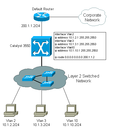
This logical diagram explains a simple interVLAN routing scenario. The scenario can be expanded to include a multi-switch environment if you first configure and test inter-switch connectivity across the network before you configure the routing capability. For such a scenario that uses a Catalyst 3550, refer to Configuring InterVLAN Routing with Catalyst 3550 Series Switches.
Step-by-Step Instructions
Complete these steps in order to configure a switch to perform interVLAN routing.
- Enable routing on the switch with the ip routing command. Even if IP routing was previously enabled, this step ensures that it is activated.
Switch(config)#ip routing
Note: If the switch does not accept the ip routing command, upgrade to either SMI image Cisco IOS Software Release12.1(11)EA1 or later, or an EMI image, and repeat this step. See the Prerequisites section for more information. Tip: Check the show running-configuration . Verify whether ip routing is enabled. The command, if enabled, appears towards the top of the output.
Switch#vlan database Switch(vlan)#vlan 2 VLAN 2 added: Name: VLAN0002 Switch(vlan)#vlan 3 VLAN 3 added: Name: VLAN0003 Switch(vlan)#vlan 10 VLAN 10 added: Name: VLAN0010 Switch(vlan)#exit APPLY completed. Exiting.
Switch#configure terminal Enter configuration commands, one per line. End with CNTL/Z. Switch(config)#interface Vlan2 Switch(config-if)#ip address 10.1.2.1 255.255.255.0 Switch(config-if)#no shutdown
Switch(config)#interface FastEthernet 0/1 Switch(config-if)#no switchport Switch(config-if)#ip address 192.168.1.1 255.255.255.0 Switch(config-if)#no shutdown
Switch(config)#ip route 0.0.0.0 0.0.0.0 192.168.1.2
This video on the Cisco Support Community demonstrates how to configure the InterVLAN routing on Catalyst 3550 Series Switch:
Verify
This section provides information in order to confirm that your configuration works properly.
- show ip route — Provides a snapshot of the routing table entries.
Cat3550#show ip route Codes: C - connected, S - static, I - IGRP, R - RIP, M - mobile, B - BGP D - EIGRP, EX - EIGRP external, O - OSPF, IA - OSPF inter area N1 - OSPF NSSA external type 1, N2 - OSPF NSSA external type 2 E1 - OSPF external type 1, E2 - OSPF external type 2, i - IS-IS, su - IS-IS summary, L1 - IS-IS level-1, L2 - IS-IS level-2, ia - IS-IS inter area, * - candidate default, U - per-user static route, o - ODR, P - periodic downloaded static route Gateway of last resort is 192.168.1.2 to network 0.0.0.0 192.168.1.0/30 is subnetted, 1 subnets C 192.168.1.0 is directly connected, FastEthernet0/48 10.0.0.0/24 is subnetted, 3 subnets C 10.1.10.0 is directly connected, Vlan10 C 10.1.3.0 is directly connected, Vlan3 C 10.1.2.0 is directly connected, Vlan2 S* 0.0.0.0/0 [1/0] via 192.168.1.2
Troubleshoot
This section provides the information used in order to troubleshoot your configuration.
Troubleshoot Procedure
Here is information relevant to troubleshoot this configuration. Use these instructions in order to troubleshoot your configuration.
- Issue Internet Control Message Protocol (ICMP) pings in order to verify whether you have Layer 2 connectivity.
- If you are not able to ping between two devices on the same VLAN on the same switch, verify that your source and destination ports have devices connected to them and are assigned to the same VLAN. For more information, refer to Creating Ethernet VLANs on Catalyst Switches.
- If you are not able to ping between two devices on the same VLAN but not on the same switch, verify that trunking is configured properly and that the native VLAN matches on both sides of the trunk.
- Initiate an ICMP ping from an end device connected to the Catalyst 3550 to its corresponding VLAN interface. In this example, you can use a host on VLAN 2 (10.1.2.2) and ping interface VLAN 2 (10.1.2.1). If you are not able to ping the interface, verify that the host’s default gateway points to the corresponding VLAN interface IP address and that the subnet masks match. For example, the default gateway of the device on VLAN 2 can point to Interface VLAN 2 (10.1.2.1). Also verify the interface VLAN status by issuing the show ip interface brief command.
- If the interface status is administratively down, enter the no shutdown command in the VLAN interface configuration mode.
- If the interface status is down/down, verify the VTP configuration and that the VLANs have been added to the VLAN database. Check to see if a port is assigned to the VLAN and whether it is in the Spanning Tree forwarding state.
- Initiate a ping from an end device in one VLAN to the interface VLAN on another VLAN in order to verify that the switch routes between VLANs. In this example, ping from VLAN 2 (10.1.2.1) to Interface VLAN 3 (10.1.3.1) or Interface VLAN 10 (10.1.10.1). If the ping fails, verify that IP routing is enabled and that the VLAN interfaces status is up with the show ip interface brief command.
- Initiate a ping from the end device in one VLAN to the end device in another VLAN. For example, a device on VLAN 2 can ping a device on VLAN 3. If the ping test is successful in step 3 but fails to reach the end device on the other VLAN, verify that the default gateway on the connected device is configured correctly.
- If you are not able to reach the Internet or corporate network, verify that the default route on the 3550 points to the correct IP address on the default router. Also verify that the IP address and subnet mask on the switch are configured correctly.
There is no set recommended value of bandwidth on a VLAN interface (SVI). The default is BW 1000000 Kbit (1 Gigabit), because the route processor internal inband is only 1 Gigabit by design. The bandwidth parameter on the show interface vlan output is not fixed bandwidth used by SVI as traffic is routed on the switch backplane. The bandwidth number can be used in order to manipulate routing metrics, calculate interface load statistics, and so forth.
The Catalyst 6500 switch platform mostly forwards traffic in hardware with the exception of control/special traffic, for example, SNMP, Telnet, SSH, Routing protocols, and ARP, which has to be processed by the Supervisor, which is done in the software.
Related Information
- Configuring InterVLAN Routing with Catalyst 3550 Series Switches
- Configuring Interface Characteristics on the 3560 Series Switches
- Configuring Interface Characteristics on the 3750 Series Switches
- Configuring Layer 3 Interfaces on Catalyst 6500 Switches Running Cisco IOS
- Technical Support & Documentation — Cisco Systems