- Configure VLAN Routing and Bridging on a Router with IRB
- Contents
- Introduction
- Before You Begin
- Conventions
- Prerequisites
- Components Used
- Background Information
- VLAN Routing and Bridging Concept with IRB
- IRB Sample Configuration
- Network Diagram
- Configuration
- show Command Outputs
- Related Information
- Cisco маршрутизатор создать vlan
- Cоздание vlan
- Популярные Похожие записи:
Configure VLAN Routing and Bridging on a Router with IRB
The documentation set for this product strives to use bias-free language. For the purposes of this documentation set, bias-free is defined as language that does not imply discrimination based on age, disability, gender, racial identity, ethnic identity, sexual orientation, socioeconomic status, and intersectionality. Exceptions may be present in the documentation due to language that is hardcoded in the user interfaces of the product software, language used based on RFP documentation, or language that is used by a referenced third-party product. Learn more about how Cisco is using Inclusive Language.
Contents
Introduction
This document describes the progression of VLANs as they are implemented with a router that is routing IP, bridging IP, and bridging IP with Integrated Routing and Bridging (IRB). Also, this document provides a sample configuration on configuring the IRB feature on a router. Note: IRB has deliberately been disabled on the Catalyst 6500 Series Switches and Cisco 7600 Series Routers. For more information, please refer to the General Limitations and Restrictions section under Release Notes for Cisco IOS Release 12.1 E on the Catalyst 6000 and Cisco 7600 Supervisor Engine and MSFC.
Before You Begin
Conventions
Prerequisites
Components Used
This document is not restricted to specific software and hardware versions. The information presented in this document was created from devices in a specific lab environment. All of the devices used in this document started with a cleared (default) configuration. If you are working in a live network, ensure that you understand the potential impact of any command before using it.
Background Information
In order for a VLAN to span a router, the router must be capable of forwarding frames from one interface to another, while maintaining the VLAN header. If the router is configured for routing a Layer 3 (network layer) protocol, it will terminate the VLAN and MAC layers at the interface a frame arrives on. The MAC layer header can be maintained if the router is bridging the network layer protocol. However, regular bridging still terminates the VLAN header. Using the IRB feature in Cisco IOS ® Release 11.2 or greater, a router can be configured for routing and bridging the same network layer protocol on the same interface. This allows the VLAN header to be maintained on a frame while it transits a router from one interface to another. IRB provides the ability to route between a bridged domain and a routed domain with Bridge Group Virtual Interface (BVI). The BVI is a virtual interface within the router that acts like a normal routed interface that does not support bridging, but represents the comparable bridge group to routed interfaces within the router. The interface number of the BVI is the number of the bridge group that the virtual interface represents. The number is the link between the BVI and the bridge group. When you configure and enable routing on the BVI, packets that come in on a routed interface, which are destined for a host on a segment in a bridge group, are routed to the BVI. From the BVI, the packet is forwarded to the bridging engine, which forwards it through a bridged interface. This is forwarded based on the destination MAC address. Similarly, packets that come in on a bridged interface, but are destined for a host on a routed network, first go to the BVI. Next, the BVI forwards the packets to the routing engine before it sends them out of the routed interface. On a single physical interface, the IRB can be created with two VLAN sub-interfaces (802.1Q tagging); one VLAN sub-interface has an IP address that is used for routing, and the other VLAN sub-interface bridges between the sub-interface used for routing and the other physical interface on the router. Since the BVI represents a bridge group as a routed interface, it must be configured only with Layer 3 (L3) characteristics, such as network layer addresses. Similarly, the interfaces configured for bridging a protocol must not be configured with any L3 characteristics.
VLAN Routing and Bridging Concept with IRB
In Figure I, PCs A and B are connected to VLANs that are in turn separated by a router. This illustrates the common misconception that a single VLAN can have a router-based connection in the middle. This figure also shows the flow of the three layers of headers for a frame traversing the links from PC A to PC B. As the frame flows through the switch, the VLAN header is applied because the connection is a trunk link. There may be several VLANs communicating across the trunk. The router terminates the VLAN layer and the MAC layer. It examines the destination IP address and forwards the frame appropriately. In this case, the IP frame is to be forwarded out of the port toward PC B. This is also a VLAN trunk and so a VLAN header is applied. Although the VLAN connecting Switch 2 to the router can be called the same number as the VLAN connecting Switch 1 to the router, it is actually not the same VLAN. The original VLAN header is removed when the frame arrives at the router. A new header may be applied as the frame exits the router. This new header may include the same VLAN number that was used in the VLAN header that was stripped when the frame arrived. This is demonstrated by the fact that the IP frame moved through the router without a VLAN header attached, and was forwarded based on the contents of the IP destination address field, and not on a VLAN ID field. Because the two VLAN trunks sit on opposite sides of the router, they must be different IP subnets. In order for the two PCs to have the same subnet address, the router would have to be bridging IP on its interfaces. However, having the devices on VLANs share a common subnet does not mean that they are on the same VLAN. Figure II shows what the VLAN topology looks like. The need to readdress IP end stations during moves can be avoided by bridging IP on some or all interfaces in the router connecting the VLANs. However, this eliminates all of the benefits of building router-based networks to control broadcasts at the network layer. Figure III shows what changes occur when the router is configured for bridging IP. Figure IV shows what happens when the router is configured for bridging IP with IRB. Figure III shows that the router is now bridging IP. Both PCs are now on the same subnet. Note: The router (bridge) now forwards the MAC layer header across to the outward-bound interface. The router still terminates the VLAN header and applies a new header prior to sending the frame out to PC B. Figure IV shows what happens when IRB is configured. The VLAN now spans the router, and the VLAN header is maintained as the frame transits the router.
IRB Sample Configuration
This configuration is an example of IRB. The configuration allows bridging IP between two Ethernet interfaces, and routing IP from bridged interfaces using a Bridged Virtual Interface (BVI). In the following network diagram, when PC_A attempts to contact PC_B, the router R1 detects that the destination’s (PC_B) IP address is in the same subnet, so the packets are bridged by router R1 between interface E0 and E1. When PC_A or PC_B attempt to contact PC_C, the router R1 detects that the destination’s (PC_C) IP address is in a different subnet, and the packet is routed using the BVI. This way, IP protocol is bridged as well as routed on the same router.
Network Diagram
Configuration
Current configuration: ! version 12.0 service timestamps debug uptime service timestamps log uptime no service password-encryption ! hostname R1 ! ! ip subnet-zero no ip domain-lookup bridge irb !-- This command enables the IRB feature on this router. ! ! ! interface Ethernet0 no ip address no ip directed-broadcast bridge-group 1 !-- The interface E0 is in bridge-group 1. ! Interface Ethernet1 no ip address no ip directed-broadcast bridge-group 1 !-- The interface E1 is in bridge-group 1. ! Interface Serial0 ip address 10.10.20.1 255.255.255.0 no ip directed-broadcast no ip mroute-cache no fair-queue ! interface Serial1 no ip address no ip directed-broadcast shutdown ! interface BVI1 ip address 10.10.10.1 255.255.255.0 !-- An ip address is assigned to the logical BVI for routing !-- IP between bridged interfaces and routed interfaces. no ip directed-broadcast ! ip classless ip route 10.10.30.0 255.255.255.0 10.10.20.2 ! bridge 1 protocol ieee !-- This command enables the bridging on this router. bridge 1 route ip !-- This command enable bridging as well routing for IP protocol. ! line con 0 transport input none line aux 0 line vty 0 4 ! end
show Command Outputs
show interfaces [ interface ] irb This command displays the protocols that can be routed or bridged for the specified interface, as follows:
R1#show interface e0 irb Ethernet0 Routed protocols on Ethernet0: ip Bridged protocols on Ethernet0: ip ipx !-- IP protocol is routed as well as bridged. Software MAC address filter on Ethernet0 Hash Len Address Matches Act Type 0x00: 0 ffff.ffff.ffff 0 RCV Physical broadcast 0x2A: 0 0900.2b01.0001 0 RCV DEC spanning tree 0x9E: 0 0000.0c3a.5092 0 RCV Interface MAC address 0x9E: 1 0000.0c3a.5092 0 RCV Bridge-group Virtual Interface 0xC0: 0 0100.0ccc.cccc 157 RCV CDP 0xC2: 0 0180.c200.0000 0 RCV IEEE spanning tree 0xC2: 1 0180.c200.0000 0 RCV IBM spanning tree R1#
Related Information
Cisco маршрутизатор создать vlan
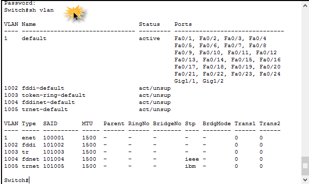
Добрый день уважаемые читатели, сегодня я вам расскажу как как происходит создание vlan, что такое VLAn написано по ссылке слева, теперь давайте его создадим, так как только практика позволяет все осознать на сто процентов. Для начала посмотрим список vlan, делается в обычном режиме командной строки. Для этого воспользуемся командой.
Cоздание vlan
Переходим от слов к делу и делаем vlan на cisco,
Видим что есть vlan 1 и все порты по умолчанию в нем.
Как создать и настроить vlan в Cisco на примере Cisco 2960+48TC-S-01
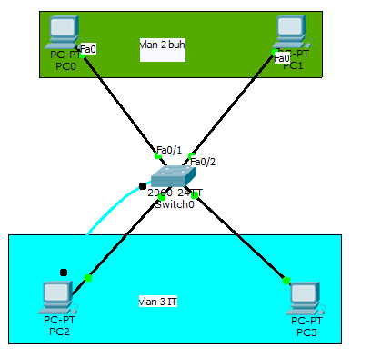
Создадим vlan 2 для отдела бухгалтерии. Заходим в режим конфигурирования.
Как создать и настроить vlan в Cisco на примере Cisco 2960+48TC-S-02
Как создать и настроить vlan в Cisco на примере Cisco 2960+48TC-S-03
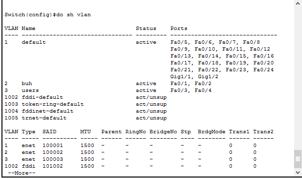
Теперь подключим интерфейсы Fa0/1 и Fa0/2 к которым подключены компьютеры бухгалтерии к vlan2
interface fastEthernet 0/1
Как создать и настроить vlan в Cisco на примере Cisco 2960+48TC-S-04
Теперь переключим vlan для данного интерфейса.
switchport access vlan 2
Как создать и настроить vlan в Cisco на примере Cisco 2960+48TC-S-05
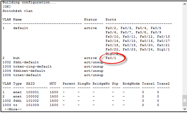
Вводим sh vlan и видим появился vlan 2 и в нем нужный интерфейс.
Как создать и настроить vlan в Cisco на примере Cisco 2960+48TC-S-06
Сделаем тоже самое для Fa0/2
interface fastEthernet 0/2
switchport access vlan 2
end
Как создать и настроить vlan в Cisco на примере Cisco 2960+48TC-S-07
Как создать и настроить vlan в Cisco на примере Cisco 2960+48TC-S-08
Как создать и настроить vlan в Cisco на примере Cisco 2960+48TC-S-09
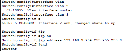
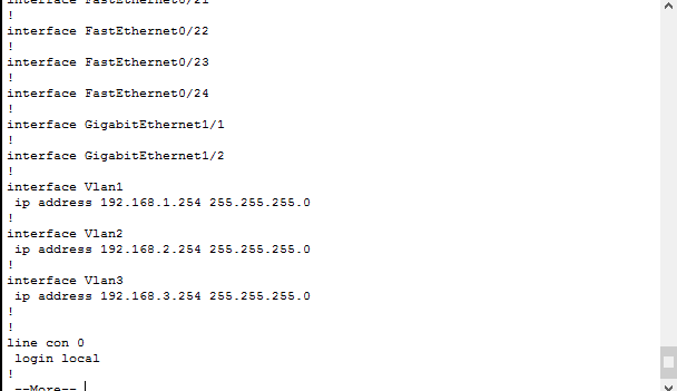
Добавим vlan 3 ip адрес 192.168.3.254
interface vlan 3
ip address 192.168.3.254 255.255.255.0
Как создать и настроить vlan в Cisco на примере Cisco 2960+48TC-S10
Теперь проверим наш ip на vlan3 на vlan 2 я настраивал аналогично
Как создать и настроить vlan в Cisco на примере Cisco 2960+48TC-S11
Теперь подключим интерфейсы Fa0/3 и Fa0/4 к которым подключены компьютеры пользователей к vlan3
interface fastEthernet 0/3
switchport access vlan 3
exit
interface fastEthernet 0/4
switchport access vlan 3
wr
Как создать и настроить vlan в Cisco на примере Cisco 2960+48TC-S12
Как создать и настроить vlan в Cisco на примере Cisco 2960+48TC-S13
Как создать и настроить vlan в Cisco на примере Cisco 2960+48TC-S14
Как создать и настроить vlan в Cisco на примере Cisco 2960+48TC-S15
На этом все vlan настроены в следующей части мы поговорим про trunk порты которые позволяют настроить коммутатор в коммутатор
Популярные Похожие записи:
Установка и настройка dongleserver ProMAX
Виртуальная машина ESXI получает неправильные настройки сети
- Установка esxi 6.5, с правильной настройкой
- Настройка сети в CentOS 8, за минуту
Подключение ключа 1С через dongleserver ProMAX
Как узнать GUID сетевого интерфейса за минуту

