- Plusivo Micro WiFi Development Board with ESP8266 and CH340G
- Specifications
- Instructions for Use
- Ks0354 Keyestudio ESP8266 WI-FI Development Board
- Technical Details
- Element and Interfaces
- Specialized Functions of Some Pins
- Detailed Using Methods are as follows:
- Step1| Install the Arduino IDE
- Step2| Installing the Driver
- Step3| Installing the ESP8266 with Arduino
- Step4| Add the Libraries
- Step5| Select the Board and Serial Port
- Step6| Upload the Code
- Step7| What Should You See
- Package List
- More Resources
Plusivo Micro WiFi Development Board with ESP8266 and CH340G
The WiFi module of V3 Lua integrates ESP8266 + additional memory 32Mbit FLASH, USB serial port ch340g WiFi + Modern ESP8266 32Mbit , the module is based on an extensive exploration ESP8266 system chip from expressif. WiFi modern ESP8266 + 32 M bit , compatible with nodemcu board.
We add an additional memory size of 32 M bit . It’s better to do big projects for big libraries. You don’t have to worry about the size of the memory. There are usb-ttl serial converter ch340g and micro USB socket on board. DC 4 ~ 9v PowerIn pin VIN. Pin header 2.54mm (0.1″) 15 X 2-wire pin settings. Do not solder. Combine WiFi access point and special station + microcontroller with simple programming language based on Lua.
WiFi modern ESP8266 + 32 M bit , provide: arduin0 Hardware IO. 10 d0-d10 can be applied in the arduin0 IDE event-driven API network, PWM function programming, IIC and SPI communication, WiFi wireless network single and ADC (A0, etc.) on one board can be used as access points and / Or station, host server), connect to the Internet, obtain or upload data. Developing countries can use the installation board.
Specifications
- Equipped with ESP8266
- Flash memory: 32 MB
- Driver serial: CH340G
- Power plug: mini USB
- Supply voltage: 5 V — 9 V DC
- 9 digital pins
- 3 3.3 V outputs
- Functions: PWM, ADC
- Communication protocols: SPI, I 2 C
Instructions for Use
The Plusivo Micro development board is not included in the Arduino IDE development environment, so you need to add it yourself. This is done as follows:
- Open Arduino IDE.
- Go to FILE> PREFERENCES.
- Copy the following link to «Additional Boards Manager URLs»: http://arduino.esp8266.com/stable/package_esp8266com_index.json
- Open TOOLS> BOARDS> BOARDS MANAGER.
- Download and install ESP8266.
- Restart the Arduino IDE.
IMPORTANT. If your operating system is Windows or MAC OS, you need to install the driver that is attached at the bottom of the page.
Now you need to select the board. Plusivo Micro is compatible with Plusivo D1 R2 & MINI. Open the TOOLS> BOARD tab and select Plusivo D1 R2 & Mini.
The configuration settings are as follows:
To test the development board functionality, you can upload an example. To choose one, go to FILE> EXAMPLES and choose a general one such as BLINK or one for ESP8266 , such as ESP8266WIFI> WiFi SCAN.
Ks0354 Keyestudio ESP8266 WI-FI Development Board

This keyestudio ESP8266 WI-FI development board is based on the ESP8266-12FWIFI module developed by Ai-Thinker.
The processor ESP8266 integrates the industry-leading Tensilica L106 ultra-low-power 32-bit micro MCU in a smaller package, with 16-bit Lite mode.
The main frequency supports 80MHz and 160 MHz.
It supports RTOS, integrated with Wi-Fi MAC/BB/RF/PA/LNA. Onboard comes with curved antenna.
This development board is a standalone network controller, which can add networking function to those existing devices.
It has 11 I/O ports (4 of which can be used as PWM output), and all I/O ports operate at 3.3V. It also comes with an AD input interface, supporting the voltage range of 0-3.3V.
The board can be powered via the USB port, or with an external power supply (DC 7-12V), or powered by the female headers Vin/GND (DC 7-12V).
Technical Details
- Microcontroller: ESP8266-12F
- Operating Voltage: 3V3
- Input Voltage (recommended): DC 7-12V
- Digital I/O Pins: 8 (GPIO2, GPIO4, GPIO5, GPIO12, GPIO13, GPIO14, GPIO15, GPIO16)
- Analog Input Pins: 1 (A0)
- IO output maximum current: 12 mA
- Main frequency supports 80 MHz and 160 MHz
- LED_BUILTIN: GPIO 14
- Comes with an external power jack (DC 7-12V)
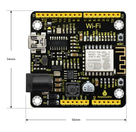
- Dimensions: 54mm*56mm*15mm
Element and Interfaces
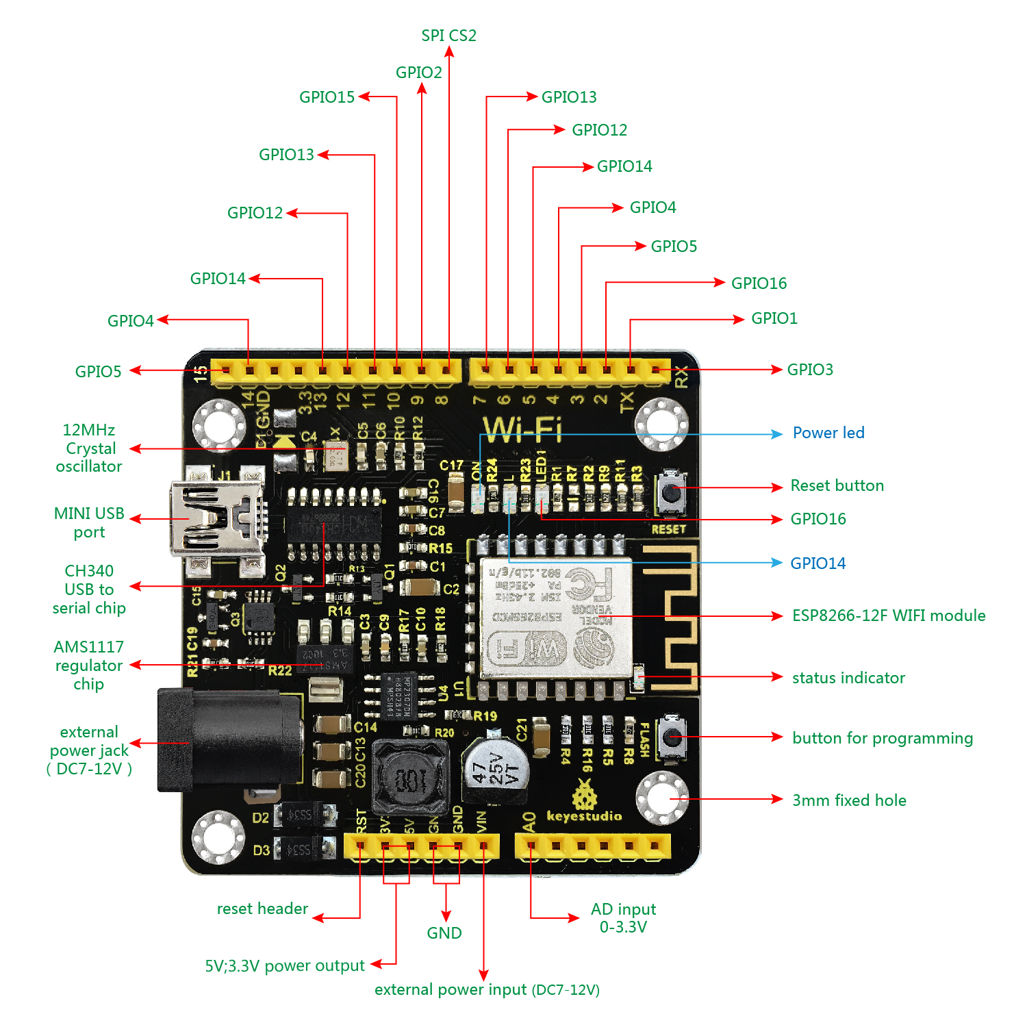
Here is an explanation of what every element and interface of the board does:
Specialized Functions of Some Pins
- Serial communication: ‘ GPIO3 (RX) and GPIO1 (TX).
- PWM Interfaces (Pulse-Width Modulation): GPIO 4, GPIO 12, GPIO 14, GPIO 15.
- SPI communication ports: GPIO6(CLK), GPIO7(MISO), GPIO8(MOSI), GPIO9(HD), GPIO10(WP), GPIO1(CS1), GPIO0(CS2)
- IIC communication: GPIO2(SDA); GPIO14(SCL)
- IR Remote Control Interface: GPIO5(IR RX); GPIO14(IR TX)
Detailed Using Methods are as follows:
Step1| Install the Arduino IDE
When programming the control board, first you should install the Arduinosoftware and driver.
You can download the different versions for different systems from the link below:
https://www.arduino.cc/en/Main/OldSoftwareReleases#1.5.x
NOTE: this control board is only compatible with Arduino 1.6.5 version or latest.
In the following, we will download the Arduino 1.6.5 version.
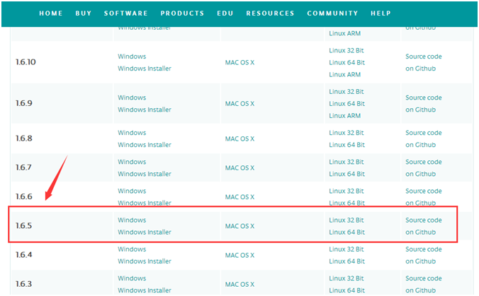

In this Windows system page, there are two options. One is Windows version, the other is Windows Installer.
For Windows Installer, you can download the installation file, this way you need to install the arduino IDE.

For simple Windows version, you can download the software directly, do not need to install, just directly use the software after unzip the file.

Next, we click the Windows, pop up the interface as below.
Click JUST DOWNLOAD.When the ZIP file is downloaded well to your computer, you can directly unzip the file. Open the Arduino-1.6.5-r5 folder, you should get it as follows.
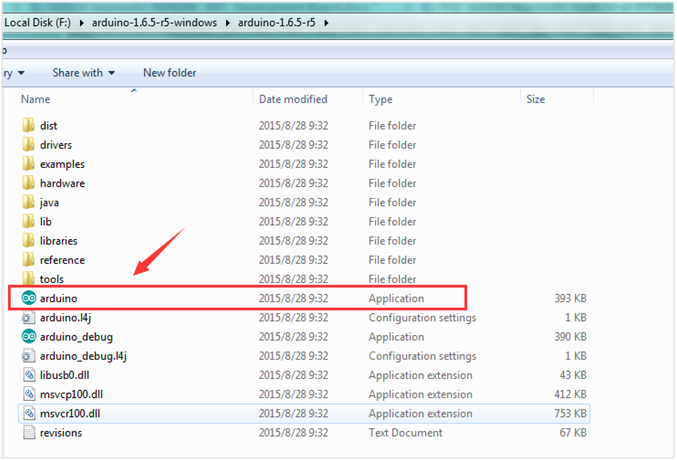
Click the icon of ARDUINO software to open it. This is your Arduino.
Step2| Installing the Driver
The USB to serial port chip of this control board is CH340G. So you need to install the driver for the chip. You can click the driver file here usb_ch341_3.1.2009.06 to download it.
In different systems, the driver installation is similar. Here we start to install the driver on the Win7 system.
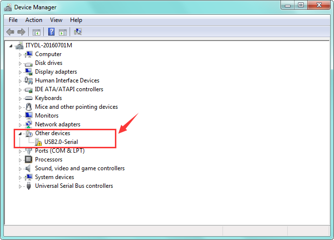
Plug one end of your USB cable into the Keyestudio ESP8266 WI-FI board and the other into a USB socket on your computer.
When you connect the ESP8266 WI-FI board to your computer at the first time, right click your “Computer” —>for “Properties”—> click the “Device manager”, under Other devices, you should see the “USB2.0-Serial”.
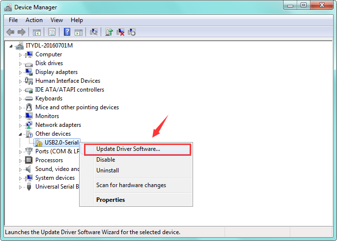
Then right-click on the device and select the top menu option (Update Driver Software. ) shown as the figure below.
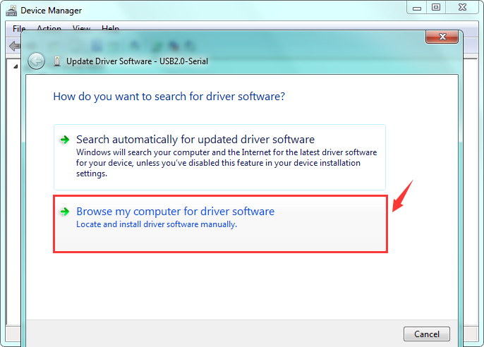
Then it will be prompted to either “Search Automatically forupdated driversoftware” or “Browse my computer for driver software”. Shown as below. In this page, select “Browse my computer for driver software”.

After that, select the option to browseand navigate to the “drivers” folder of usb-ch341 installation.
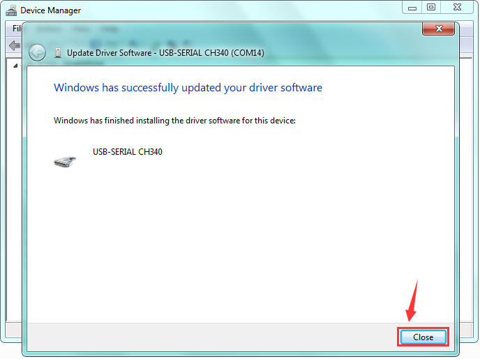
Once the software has been installed, you will get a confirmation message. Installation completed, click “Close”.

Up to now, the driver is installed well. Then you can right click “Computer” —>“Properties”—>“Device manager”, you should see the device as the figure shown below.
Step3| Installing the ESP8266 with Arduino
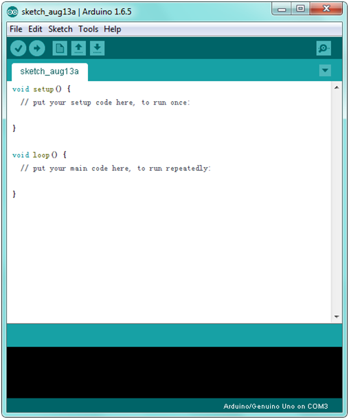
Double-click the icon of Arduino software downloaded well, you will get the interface shown below.
(Note: if the Arduino software loads in the wrong language, you can change it in the preferences dialog. See the environment page for details.)
![]()
The functions of each button on the Toolbar are listed below:
| Verify/Compile | Check the code for errors |
|---|---|
| Upload | Upload the current Sketch to the Arduino |
| New | Create a new blank Sketch |
| Open | Show a list of Sketches |
| Save | Save the current Sketch |
| Serial Monitor | Display the serial data being sent from the Arduino |
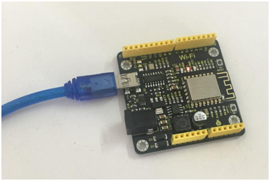
First, plug one end of your USB cable into the Keyestudio ESP8266 WI-FI board and the other into a USB socket on your computer.
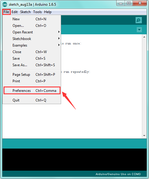
Then open the Arduino IDE, click the “File” to select the “Preferences”.
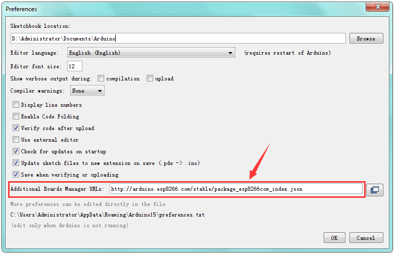
The pop-up interface is shown below. See the “Additional Boards Manager URLs”, copy and paste the link: http://arduino.esp8266.com/stable/package_esp8266com_index.json and then click OK.

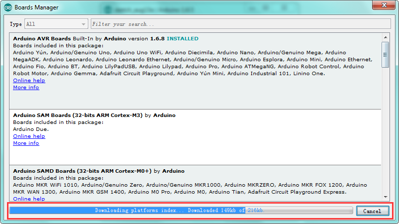
After that, click “Tools”, for “Board”, enter theBoards Manager, it will automatically download the relevant file. Shown below.
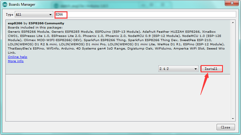
Done downloading the relevant file, it will pop up the window below. Then enter the 8266 on the blank bar and click Install.
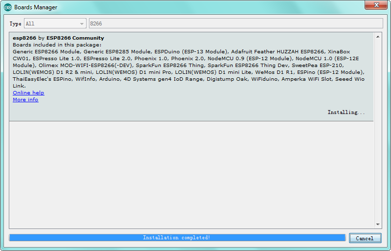
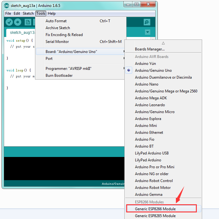
Installation completed, click Close, then click “Tools”, for “Board”, you should see the Generic ESP8266 Module. Shown below.
Step4| Add the Libraries
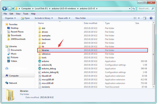
Before upload the code to test your board, you should first add all the libraries into the libraries folder of Arduino-1.6.5-r5. You can click the link to download all the libraries needed.
https://drive.google.com/open?id=11mTs_DbCIx-PQHPjfZOAekBZ7IL8al3D
Step5| Select the Board and Serial Port
Open the Arduino IDE, you’ll need to click the “Tools”, then select the Board and the Serial Port.
You can check the Serial Port on your computer’s Device Manager.
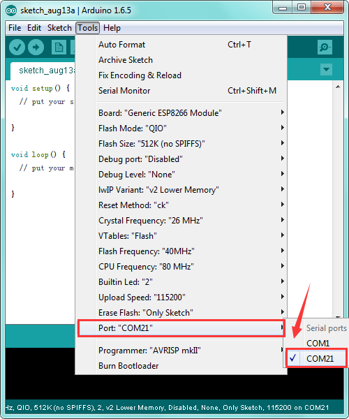
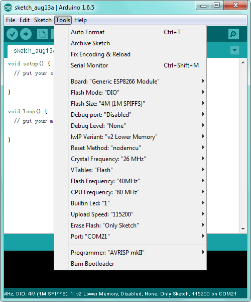
Below is the complete settings you should refer to:
Step6| Upload the Code
Add well all the libraries mentioned above, and select well the Board and Port, you should upload the code to test your board.
Below is an example code, you can copy and paste it on Arduino IDE. Or dowload the code here
#include "ESP8266WiFi.h" void setup() < Serial.begin(115200); // Set WiFi to station mode and disconnect from an AP if it was previously connected WiFi.mode(WIFI_STA); WiFi.disconnect(); delay(100); Serial.println("Setup done"); >void loop() < Serial.println("scan start"); // WiFi.scanNetworks will return the number of networks found int n = WiFi.scanNetworks(); Serial.println("scan done"); if (n == 0) Serial.println("no networks found"); else < Serial.print(n); Serial.println(" networks found"); for (int i = 0; i < n; ++i) < // Print SSID and RSSI for each network found Serial.print(i + 1); Serial.print(": "); Serial.print(WiFi.SSID(i)); Serial.print(" ("); Serial.print(WiFi.RSSI(i)); Serial.print(")"); Serial.println((WiFi.encryptionType(i) == ENC_TYPE_NONE)?" ":"*"); delay(10); >> Serial.println(""); // Wait a bit before scanning again delay(5000); > 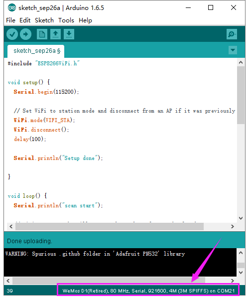
After copy and paste the code on IDE, click the compile button, if compiling successfully, the message «Done compiling.» will appear in the status bar. Then click the “Upload” button, if the upload is successful, the message «Done uploading.» will appear in the status bar.
Step7| What Should You See

Done uploading the code, open the serial monitor and set the baud rate to 115200, it can search the WIFI name nearby.
Package List