- ¶ Introduction
- ¶ Other guides in this series
- ¶ Gather Information About Your Printer
- ¶ What do we need to know?
- ¶ RepRapFirmware Config Tool — Overview
- ¶ Config Tool — General
- ¶ Config Tool — I/O Mapping
- ¶ Config Tool — Motors
- ¶ Config Tool — Endstops
- ¶ Config Tool — Heaters
- ¶ Config Tool — Fans
- ¶ Config Tool — Tools
- ¶ Config Tool — Compensation
- ¶ Config Tool — Display
- ¶ Config Tool — Network
- ¶ Config Tool — Finish
- ¶ Preparing the SD card
- ¶ Commissioning
¶ Introduction
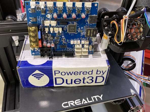
In the previous guide, we mounted the Duet 3 Mini 5+ board inside the Ender 3 and connected all the wires.
Before we can use the Duet, we need to provide it with configuration information specific to the printer.
This guide will go through how to obtain the needed information, and how to go through the online configuration tool to generate a set of config files that will work with the Ender 3.
Even though this guide is specific to the Ender 3, the general principles remain the same for other printers, and could be used as a basis for adapting printers.
¶ Other guides in this series
- Part 1 — Wiring
- Part 2 — Configuration
- Part 3 — Commissioning
- Part 4 — Calibration
- Part 5 — Single Board Computer
¶ Gather Information About Your Printer
Before we can properly configure the Duet with RepRapFirmware, we must gather a list of parameters that define the mechanical operation of the printer itself. This information can be found in multiple places and will vary from printer to printer.
 In the case of the Ender 3 Pro, Creality provides a download for the Marlin configuration used. You can download the Creality Ender 3 Marlin Config here: https://www.creality.com/download
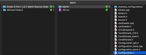
The SD card that came with your Ender 3 printer may also include a copy of the Marlin files. The Marlin file we require is Configuration.h.
Some of this information can also be accessed via the LCD menu on the printer if you look at it before you start the conversion. It can help to write these values down for future reference.
¶ What do we need to know?
The more details we know about the physical, electrical, and mechanical aspects of the printer, the easier it will be to complete the Configuration Tool.
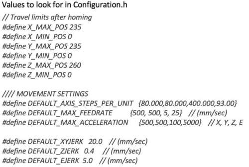
- Build volume in X Y Z
- PSU Voltage
- Heater Max Temps
- Motor Currents
- Endstop locations and type
- Thermistor type and configuration values
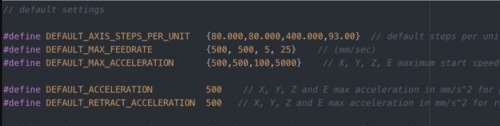
- Axis steps per mm
- Max Speed, acceleration and jerk values.
This guide assumes you are using the stock Ender 3 kit, and have it wired to the Mini 5+ as shown in part 1 of this guide.
Some values are tied to the physical qualities of the printer and cannot be changed. Other values, such as speed, acceleration, and jerk can be changed to suit your requirements. A future guide will go through calibration and tuning to find the best values, but for now we will use the stock values.
Warning! Be aware that Marlin uses mm/s for most of its speed values, while RepRapFirmware uses mm/min. The two can be converted by either multiplying or dividing by 60.
¶ RepRapFirmware Config Tool — Overview
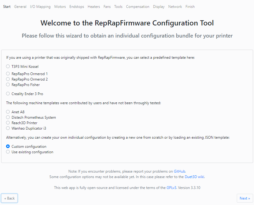
Go to https://configtool.reprapfirmware.org/ to begin. Choose a custom printer for this example.
The rest of the guide will go through each page and describe what we need to change to match the Ender 3. Only changed values will be listed. Match your values to those shown in the screen shots.
At the end we will download a zip file that will replace the /sys folder on the SD card. This folder contains all the configuration files that define how the Mini 5+ is configured and how it behaves during certain operations like homing.
¶ Config Tool — General
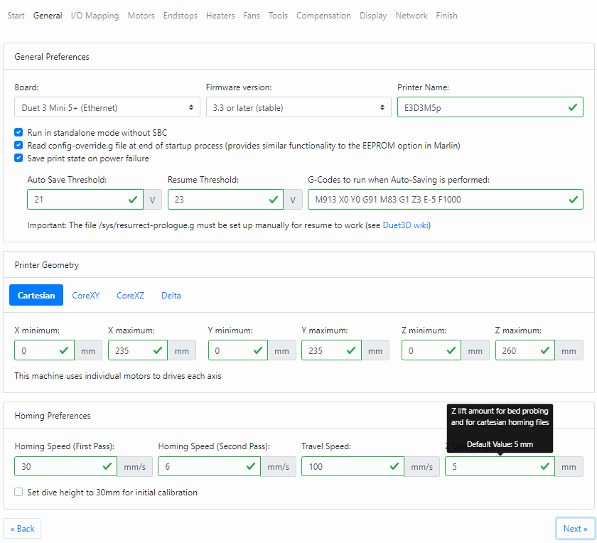
The General Tab is used to define a few basic starting values like which board you are using, whether to use resume on power loss functionality, the size of your build volume, and what kinematics your printer uses.
- Select Duet 3 Mini 5 + (Ethernet) or (Wifi) depending on your version of the board.
- Give your printer a name.
- Check Run in standalone mode without SBC. (That will come later)
- Check read config-override.g
- Check save print state on power failure and set the threshold values for power save as 21v and 23v
- Maximum travel distance is X235 Y235 Z260
¶ Config Tool — I/O Mapping
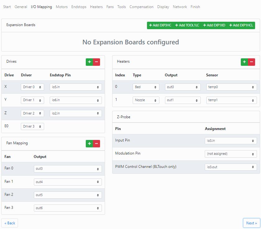
Here we will define the pins used for our drivers, endstops, heaters, fans, probe, etc.
- X as Driver_0, Y as Driver_1, Z as Driver_2, E as Driver_3
- X Endstop = io5.in, Y Endstop = io6.in, Z Endstop = io2.in.
- Heater0 (bed) = OUT0 and TEMP0. Heater1 (hotend) = OUT1 and TEMP1.
- Fan0 = out3, Fan1 = Out4, Fan2 = Out5, Fan3 = Out6 for the LED strip.
- Z-Probe will be a BLTouch, so for Input Pin choose io3.in, leave Modulation Pin unassigned, and PWM Control Channel as io3.out.
Refer to the table of pin assignments from Part 1.
¶ Config Tool — Motors
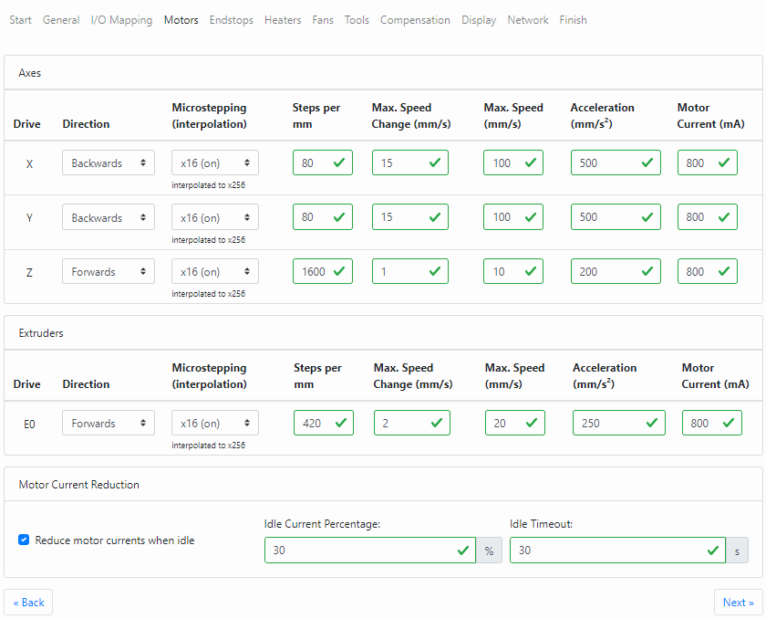
The Motors Tab defines motor directions, sets microstepping and steps per mm, motor currents, speed, acceleration, and jerk. Configure the motors page as follows:
- X: Backwards, x16 (on), 80, 15, 100, 500, 600
- Y: Backwards, x16 (on), 80, 15, 100, 500, 600
- Z: Forwards, x16 (on), 400, 1, 10, 200, 600
- E: Backwards, x16 (on), 93, 5, 60, 2500, 900
These values are found in the Marlin Configuration.h. Note that some slight changes have been made to bring it more in line with standard RepRapFirmware values.
These are starter values that can be adjusted later once you start printing, but these values are known to work well with the Ender 3.
Note that the Extruder microsteps could be set to x128 with ~740 steps per mm. This may help increase the resolution of the stock extruder drive, which is rather low due to being ungeared. This is optional. The default x16 value also works and leads to a steps per mm value of ~95. Exact value to be calibrated later.
¶ Config Tool — Endstops
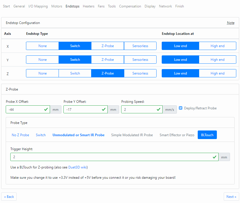
The Endstops Tab defines what type of endstop switch is being used, and whether it is located on the Low End or High End of the printer axis.
It also defines the Z Probe. The stock Ender 3 does not come with a Z probe by default, however we went through the process of adding a BLTouch in part 1 of this guide.
The Ender 3 Pro uses Active high (NC) switches and trigger at the low end of travel (X0, Y0, Z0)
For X and Y, choose switch and low end. To choose the probe for the Z axis, we must first select BLTouch below, and then Z-Probe for the Z axis, also low end.
If you already know the probe X and Y offset and trigger height add it now. Calibration of the probe offsets will happen in the next guide.
In a later guide we will manually edit the config.g to add the Z axis endstop as a Z Max endstop.
¶ Config Tool — Heaters
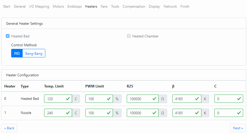
The Heaters Tab defines the bed and tool heaters, and sets the parameters of the thermistors.
Change the bed heater control method to PID.
Set the bed temp limit to 80c (limit for the magnetic bed surface)
Set the Nozzle temp limit to 250c (limit for the PTFE tube in the hotend)
Set the values for both Thermistor values as: R25 – 98801, B – 4185, C — 0
Those values are accurate for the stock Ender 3 thermistors provided by Creality. If you have a different aftermarket thermistor, you’ll need to get the values from the manufacturer, or derive them manually. Generally though, R25 = 100000 and B = 3950 is fine for a generic NTC 100k 3950 thermistor.
¶ Config Tool — Fans
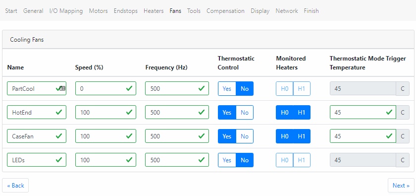
Under the name heading, rename each fan to be something notable like PartFan, HotEnd, Case, and LED.
- Fan0, 0, 500, No
- Fan1, 100, 500, Yes, Bed+E0, 45
- Fan2, 100, 500, Yes, Bed+E0, 45
- Fan3, 100, 500, No
This sets up Fan0 as the part cooling fan controlled by the slicer during a print. Fan1 is the hotend heat sink which turns on when the bed or hotend reaches 45c.
Fan2 is the case fan which also turns on when either heater is over 45, and Fan3, which is actually the LED strip, will turn on automatically at power up and can be dimmed with a slider in the web interface.
¶ Config Tool — Tools
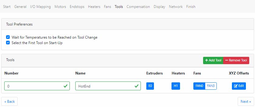
For printers with multiple tools you can use the Tools Tab to define the heater and extruder used for the tool. In the case of the Ender 3 there is only a single tool.
Check select First tool on start-up
Enter a name for the default tool if you like. This name will show up in the Duet Web Control. In this case we used the generic «HotEnd» just to differentiate it from the heat bed.
Make sure the extruder0 and heater0 are selected and choose fan0 to set the correct part cooler fan.
¶ Config Tool — Compensation
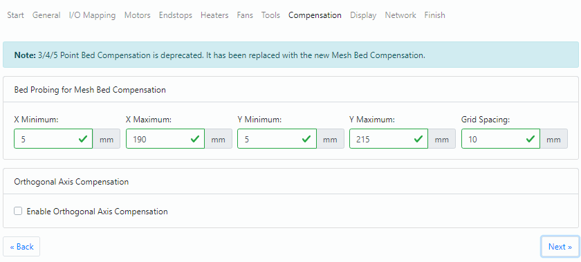
This tab defines the area of the bed to be probed when using Mesh Compensation. In config.g this is expressed as M557 and defines the area of the bed to be probed when using G29.
Typically this is used with a Z Probe, but it can actually be done manually as well.
Even though the stock Ender 3 doesn’t have a Z probe, we will define the probe area anyway just in case you add a probe in the future.
Set the area to be X min 20, X max 200, Y min 20, Y max 200, with a spacing of 20mm. This should be a safe starting point. The exact values will depend on your bed, the probe offset, and your XY travel limits.
See this guide for further information on using mesh bed compensation.
¶ Config Tool — Display
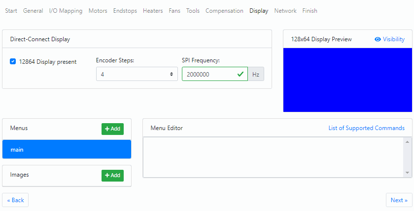
If using the stock Ender 3 display, or any other 12864 display, check the 12864 Display present box.
Once checked you’ll be able to add any custom menu files.
¶ Config Tool — Network
This tab may not be shown when using a Duet3 Mini5+ and have selected SBC mode as the Pi will handle the networking.
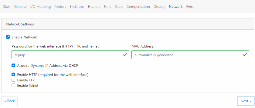
In order to connect to the web interface, we need to reliably know the IP address of the Duet. You have two options for this: Static IP versus Dynamic IP
- Set a static IP address in the config file of the Duet that falls within your network range, but which isn’t already used, or likely to be used by your router for another device in the future.
- Use DHCP to let the router choose a suitable IP address for the Duet and then use the Router control panel to reserve that IP address for future use by the Duet.
For this guide, we will be using DHCP to get an IP address from the Router as it is best practice to use DHCP to assign the address and then use the router control panel to assign the address permanently with a DHCP reservation. This prevents any possible future IP conflicts with another device on the network.
The steps for setting up a reservation will depend on your model of router and is outside the scope of this guide, but instructions can usually be found in the manual for the router.
The first screen shot shows what this tab looks like for the Ethernet Mini5+. The second screen shot shows what it looks like for the WiFi version. At the time of writing the wifi SSID and password is not used to connect and will need to be manually entered as described here: Getting Connected to your Duet.
¶ Config Tool — Finish
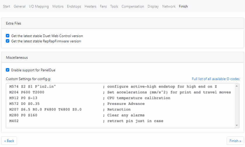
 Check the box for PanelDue support if you intend to use one.
Check the boxes to download the latest DWC and firmware files as part of the bundle.
Optionally, if you are following along with the Ender3 guide you can add the custom gcode section shown in the image to add some extra features.
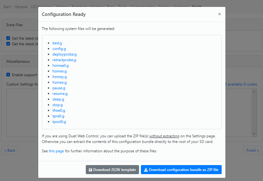
Click Finish to get your complete config file set.
Use the blue button at the bottom right to download a zip file that contains all of the necessary config files.
¶ Preparing the SD card
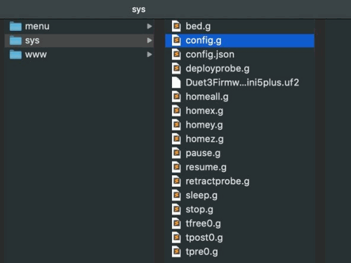
The SD card that came with the Duet 3 Mini 5+ will include the basic folder structure needed for operation and the RRF Web Configuration Tool will supply you with the necessary configuration files.
Extract the zip file that you got from the Configuration Tool and move the /menu /sys /www folders onto the SD card, replacing any files that already exist.
If you ever need to format the SD card, it’s suggested that you use FAT32 with 64kb cluster size. For best results, it’s suggested to use the SD Card Formatter.
Further details on the SD card folder structure and the files contained in the /sys folder, see here: Firmware Overview
You may want to check the Duet3D RepRapFirmware Github repository for the latest release details.
Create the following additional folders on the root of the SD card. macros, Filaments, gcodes
¶ Commissioning
This concludes the configuration guide. Now we can continue on with first commissioning of the printer in the next guide.