Содержание
Linux Device tree
The Device Tree side:
The compatible string used to bind a device with the driver:
static struct of_device_id mxs_auart_dt_ids[] = < < .compatible = "fsl,imx28-auart", .data = &mxs_auart_devtype[IMX28_AUART] >, < .compatible = "fsl,imx23-auart", .data = &mxs_auart_devtype[IMX23_AUART] >, < /* sentinel */ > >; MODULE_DEVICE_TABLE(of, mxs_auart_dt_ids); // [. ] static struct platform_driver mxs_auart_driver = < .probe = mxs_auart_probe, .remove = mxs_auart_remove, .driver = < .name = "mxs-auart", .of_match_table = mxs_auart_dt_ids, >, >; // Code from drivers/tty/serial/mxs-auart.c
- of_match_device allows to get the matching entry in the mxs_auart_dt_ids table .
- Useful to get the driver-specific data field, typically used to alter the behavior of the driver depending on the variant of the detected device.
- of_match_device allows to get the matching entry in the mxs_auart_dt_ids table
- Useful to get the driver-specific data field, typically used to alter the behavior of the driver depending on the variant of the detected device.
static int mxs_auart_probe(struct platform_device *pdev) < const struct of_device_id *of_id = of_match_device(mxs_auart_dt_ids, &pdev->dev); if (of_id) < /* Use of_id->data here */ // [. ] > // [. ] >
- Getting a reference to the clock
- described by the clocks property
- s->clk = clk_get(&pdev->dev, NULL);
- described by the reg property
- r = platform_get_resource(pdev, IORESOURCE_MEM, 0);
- described by the interrupts property
- s->irq = platform_get_irq(pdev, 0);
- described by the dmas property
- s->rx_dma_chan = dma_request_slave_channel(s->dev, «rx»);
- s->tx_dma_chan = dma_request_slave_channel(s->dev, «tx»);
- struct device_node *np = pdev->dev.of_node;
- if (of_get_property(np, «fsl,uart-has-rtscts», NULL))
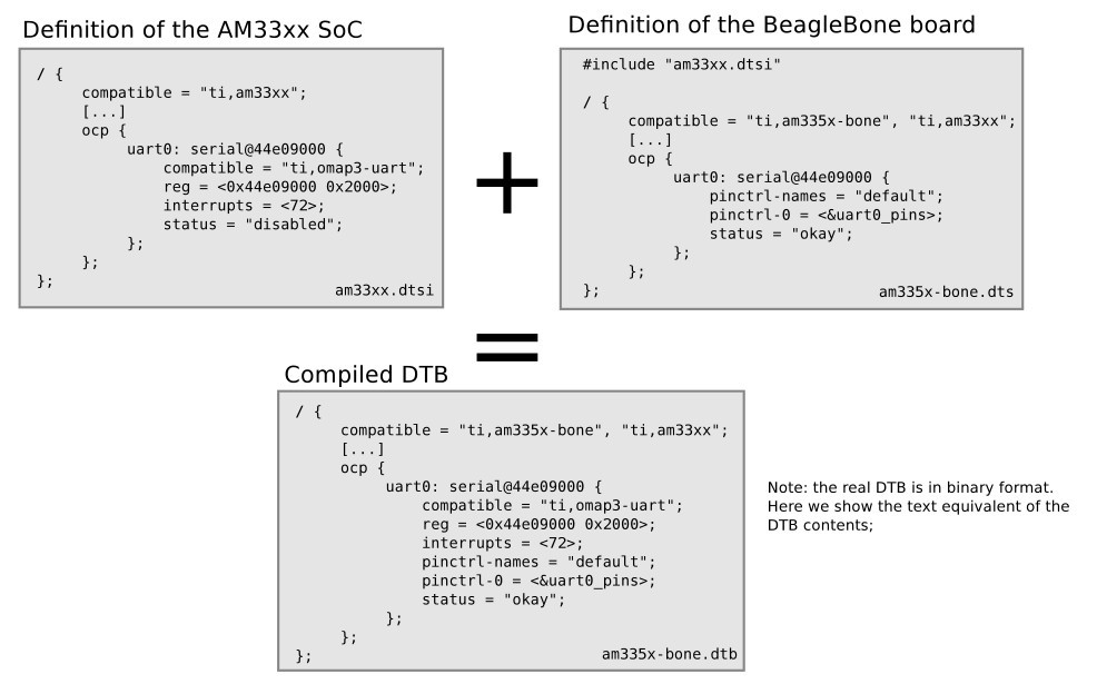
Device Tree inclusion
- Device Tree files are not monolithic, they can be split in several files, including each other.
- .dtsi files are included files, while .dts files are final Device Trees.
- Typically, .dtsi will contain definition of SoC-level information.
- The .dts file contains the board-level information.
- The inclusion works by overlaying the tree of the including file over the tree of the included file.
- Inclusion using the DT operator /include/ , or since a few kernel releases, the DTS go through the C preprocessor, so #include is recommended.

Device Tree inclusion example:
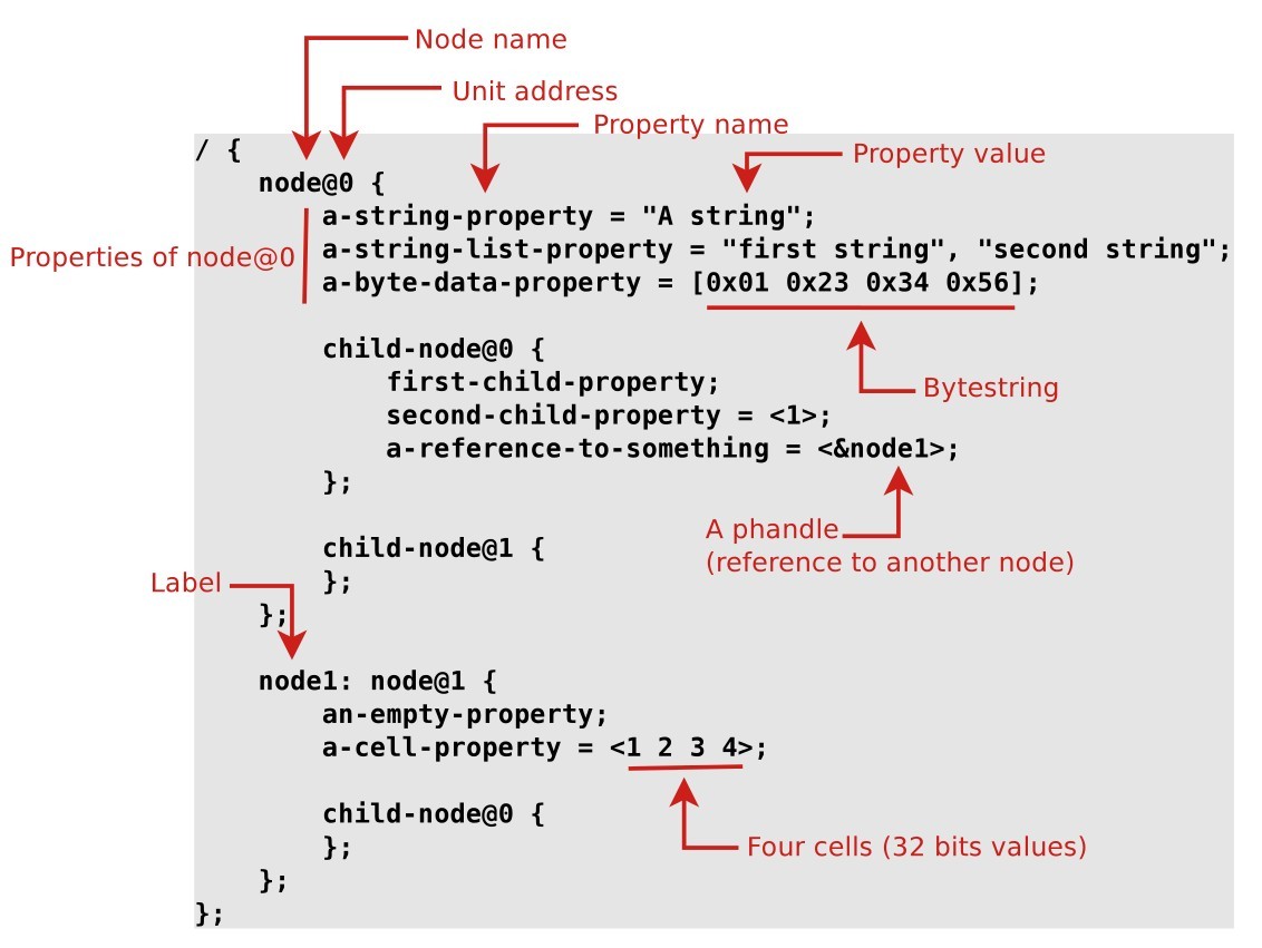
Device Tree binding
- bindings, for how specific types and classes of devices are represented in the device tree.
- The compatible property of a device node describes the specific binding (or bindings) to which the node complies.
- When creating a new device tree representation for a device, a binding should be created that fully describes the required properties and value of the device. This set of properties shall be sufficiently descriptive to provide device drivers with needed attributes of the device.
Documentation of Device Tree bindings
All Device Tree bindings recognized by the kernel are documented in Documentation/devicetree/bindings .
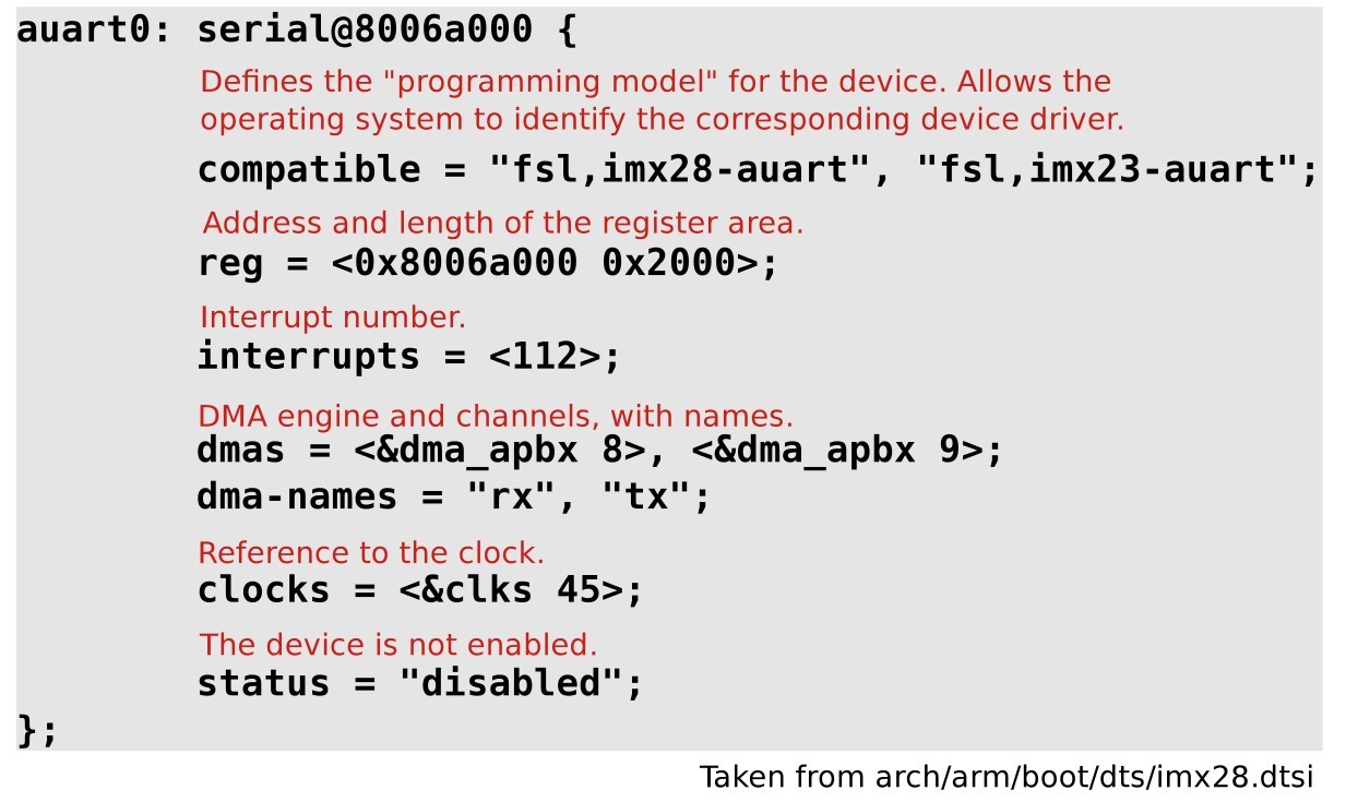
A Device Tree binding documentation example: Documentation/devicetree/bindings/tty/serial/fsl-mxs-auart.txt
*Freescale MXS Application UART (AUART) Required properties: - compatible : Should be "fsl,-auart". The supported SoCs include imx23 and imx28. - reg : Address and length of the register set for the device - interrupts : Should contain the auart interrupt numbers - dmas: DMA specifier, consisting of a phandle to DMA controller node and AUART DMA channel ID. Refer to dma.txt and fsl-mxs-dma.txt for details. - dma-names: "rx" for RX channel, "tx" for TX channel. Example: auart0: serial@8006a000 < compatible = "fsl,imx28-auart", "fsl,imx23-auart"; reg = ; interrupts = ; dmas = , ; dma-names = "rx", "tx"; >; Note: Each auart port should have an alias correctly numbered in "aliases" node. Example: [. ]
compatible property
The top-level compatible property typically defines a compatible string for the board, and then for the SoC.
Used to match with the dt_compat field of the DT_MACHINE structure:
static const char *mxs_dt_compat[] __initdata = < "fsl,imx28", "fsl,imx23", NULL, >; DT_MACHINE_START(MXS, "Freescale MXS (Device Tree)") .dt_compat = mxs_dt_compat, //[. ] MACHINE_END
Can also be used within code to test the machine:
if (of_machine_is_compatible("fsl,imx28-evk")) imx28_evk_init();
Bus, address cells and size cells
Inside a bus, one typically needs to define the following properties:
- A compatible property, which identifies the bus controller. Child nodes will be registered as platform devices.
- The #address-cells property indicate how many cells (i.e 32 bits values) are needed to form the base address part in the reg property.
- The #size-cells is the same, for the size part of the reg property.
- The ranges property can describe an address translation between the child bus and the parent bus. When simply defined as ranges; , it means that the translation is an identity translation.
i2c0: i2c@80058000 < #address-cells = ; #size-cells = ; compatible = "fsl,imx28-i2c"; reg = ; interrupts = ; #[. ] sgtl5000: codec@0a < compatible = "fsl,sgtl5000"; reg = ; VDDA-supply = ; VDDIO-supply = ; clocks = ; >; at24@51 < compatible = "at24,24c32"; pagesize = ; reg = ; >; >;
Interrupt handling
- interrupt-controller ; is a boolean property that indicates that the current node is an interrupt controller.
- #interrupt-cells indicates the number of cells in the interrupts property for the interrupts managed by the selected interrupt controller.
- interrupt-parent is a phandle that points to the interrupt controller for the current node. There is generally a top-level interrupt-parent definition for the main interrupt controller.
/ < interrupt-parent = ; apb@80000000 < apbh@80000000 < icoll: interrupt-controller@80000000 < compatible = "fsl,imx28-icoll", "fsl,icoll"; interrupt-controller; #interrupt-cells = ; reg = ; >; ssp0: ssp@80010000 < #[. ] interrupts = ; >; >; >; >;
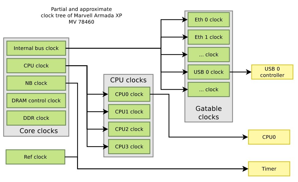
Clock tree example, Marvell Armada XP
soc < coreclk: mvebu-sar@18230 < compatible = "marvell,armada-xp-core-clock"; reg = ; #clock-cells = ; >; cpuclk: clock-complex@18700 < #clock-cells = ; compatible = "marvell,armada-xp-cpu-clock"; reg = ; clocks = ; >; gateclk: clock-gating-control@18220 < compatible = "marvell,armada-xp-gating-clock"; reg = ; clocks = ; #clock-cells = ; >; > clocks < /* 25 MHz reference crystal */ refclk: oscillator < compatible = "fixed-clock"; #clock-cells = ; clock-frequency = ; >; >;
cpu@0 < device_type = "cpu"; compatible = "marvell,sheeva-v7"; reg = ; clocks = ; >;
timer@20300 < compatible = "marvell,armada-xp-timer"; clocks = , ; clock-names = "nbclk", "fixed"; >;
usb@52000 < compatible = "marvell,orion-ehci"; reg = ; interrupts = ; clocks = ; status = "disabled"; >;
pinctrl binding
- The pinctrl subsystem allows to manage pin muxing.
- In the Device Tree, devices that need pins to be muxed in a certain way must declare the pinctrl configuration they need.
- The pinctrl- properties allow to give the list of pinctrl configuration needed for a certain state of the device.
- The pinctrl-names property allows to give a name to each state.
- When a device is probed, its default pinctrl state is requested automatically.
ssp0: ssp@80010000 < pinctrl-names = "default"; pinctrl-0 = ; [. ] >;- A pinctrl configuration provides a list of pins and their configuration.
- Such configurations are defined as sub-nodes of the pinctrl device, either at the SoC-level, or board-level.
- The binding for such configurations is highly dependent on the specific pinctrl driver being used.
mmc0_8bit_pins_a: mmc0-8bit@0 < fsl,pinmux-ids = < 0x2000 /* MX28_PAD_SSP0_DATA0__SSP0_D0 */ 0x2010 /* MX28_PAD_SSP0_DATA1__SSP0_D1 */ [. ] 0x2090 /* MX28_PAD_SSP0_DETECT__SSP0_. */ 0x20a0 /* MX28_PAD_SSP0_SCK__SSP0_SCK */ >; fsl,drive-strength = ; fsl,voltage = ; fsl,pull-up = ; >;pmx_nand: pmx-nand < marvell,pins = "mpp0", "mpp1", "mpp2", "mpp3", "mpp4", "mpp5", "mpp18", "mpp19"; marvell,function = "nand"; >;
More references
- Device Tree for Dummies — The Linux Foundation
- Device Tree Usage: how to write a device tree for a new machine
- DeviceTree.org website, http://www.devicetree.org
- Device Tree Specification Release 0.1
- Device Tree documentation in the kernel sources, Documentation/devicetree
Created: 2016-12-11 Sun 22:42