- Saved searches
- Use saved searches to filter your results more quickly
- License
- pschatzmann/ESP32-A2DP
- Name already in use
- Sign In Required
- Launching GitHub Desktop
- Launching GitHub Desktop
- Launching Xcode
- Launching Visual Studio Code
- Latest commit
- Git stats
- Files
- README.md
- About
- Using an ESP32 and PCM5102 as a Bluetooth audio receiver
- Share this:
- Related
Saved searches
Use saved searches to filter your results more quickly
You signed in with another tab or window. Reload to refresh your session. You signed out in another tab or window. Reload to refresh your session. You switched accounts on another tab or window. Reload to refresh your session.
A Simple ESP32 Bluetooth A2DP Library (to implement a Music Receiver or Sender) that supports Arduino, PlatformIO and Espressif IDF
License
pschatzmann/ESP32-A2DP
This commit does not belong to any branch on this repository, and may belong to a fork outside of the repository.
Name already in use
A tag already exists with the provided branch name. Many Git commands accept both tag and branch names, so creating this branch may cause unexpected behavior. Are you sure you want to create this branch?
Sign In Required
Please sign in to use Codespaces.
Launching GitHub Desktop
If nothing happens, download GitHub Desktop and try again.
Launching GitHub Desktop
If nothing happens, download GitHub Desktop and try again.
Launching Xcode
If nothing happens, download Xcode and try again.
Launching Visual Studio Code
Your codespace will open once ready.
There was a problem preparing your codespace, please try again.
Latest commit
Git stats
Files
Failed to load latest commit information.
README.md
A Simple Arduino Bluetooth Music Receiver and Sender for the ESP32
The ESP32 is a microcontroller that provides an API for Bluetooth A2DP which can be used to receive sound data e.g. from your Mobile Phone and makes it available via a callback method. The output is a PCM data stream, decoded from SBC format. The documentation can be found here.
I2S is an electrical serial bus interface standard used for connecting digital audio devices together. It is used to communicate PCM audio data between integrated circuits in an electronic device.
So we can just feed the input from Bluetooth to the I2S output: An example for this from Espressif can be found on Github.
Unfortunately this example did not make me happy so I decided to convert it into a simple Arduino Library that is very easy to use from an Arduino Software IDE.
Supported Bluetooth Protocols
As the name of this libariy implies, it supports the A2DP Bluetooth protocol which only provides audio streaming!
It also supports Audio/Video Remote Control Profile (AVRCP) together with A2DP.
The Hands-Free Profile (HFP), Headset Profile (HSP) and stand alone AVRCP without A2DP are not supported!
This can be used e.g. to build your own Bluetooth Speaker.
A Simple I2S Example (A2DS Sink) using default Pins
Here is the simplest example which just uses the proper default settings:
#include "BluetoothA2DPSink.h" BluetoothA2DPSink a2dp_sink; void setup() < a2dp_sink.start("MyMusic"); >void loop() This creates a new Bluetooth device with the name “MyMusic” and the output will be sent to the following default I2S pins which need to be conected to an external DAC:
You can define your own pins easily by calling the set_pin_config method in the setup before the start .
#include "BluetoothA2DPSink.h" BluetoothA2DPSink a2dp_sink; void setup() < i2s_pin_config_t my_pin_config = < .bck_io_num = 26, .ws_io_num = 25, .data_out_num = 22, .data_in_num = I2S_PIN_NO_CHANGE >; a2dp_sink.set_pin_config(my_pin_config); a2dp_sink.start("MyMusic"); > void loop() Using your specific i2s_config
In some cases you might want to use your specific i2s_config settings. E.g. to request a different bits_per_sample (e.g. 32) or to use the use_apll or to optimize the dma buffer.
#include "BluetoothA2DPSink.h" BluetoothA2DPSink a2dp_sink; void setup() < static i2s_config_t i2s_config = < .mode = (i2s_mode_t) (I2S_MODE_MASTER | I2S_MODE_TX), .sample_rate = 44100, // updated automatically by A2DP .bits_per_sample = (i2s_bits_per_sample_t)32, .channel_format = I2S_CHANNEL_FMT_RIGHT_LEFT, .communication_format = (i2s_comm_format_t) (I2S_COMM_FORMAT_STAND_I2S), .intr_alloc_flags = 0, // default interrupt priority .dma_buf_count = 8, .dma_buf_len = 64, .use_apll = true, .tx_desc_auto_clear = true // avoiding noise in case of data unavailability >; a2dp_sink.set_i2s_config(i2s_config); a2dp_sink.start("MyMusic"); > void loop() Output to the Internal DAC
You can also send the output directly to the internal DAC of the ESP32 by providing the corresponding i2s_config:
#include "BluetoothA2DPSink.h" BluetoothA2DPSink a2dp_sink; void setup() < static const i2s_config_t i2s_config = < .mode = (i2s_mode_t) (I2S_MODE_MASTER | I2S_MODE_TX | I2S_MODE_DAC_BUILT_IN), .sample_rate = 44100, // corrected by info from bluetooth .bits_per_sample = (i2s_bits_per_sample_t) 16, /* the DAC module will only take the 8bits from MSB */ .channel_format = I2S_CHANNEL_FMT_RIGHT_LEFT, .communication_format = (i2s_comm_format_t)I2S_COMM_FORMAT_STAND_MSB, .intr_alloc_flags = 0, // default interrupt priority .dma_buf_count = 8, .dma_buf_len = 64, .use_apll = false >; a2dp_sink.set_i2s_config(i2s_config); a2dp_sink.start("MyMusic"); > void loop() The output goes now to the DAC pins GPIO25 (Channel 1) and GPIO26 (Channel 2).
Accessing the Sink Data Stream with Callbacks
You can be notified when a packet is received. The API is using PCM data normally formatted as 44.1kHz sampling rate, two-channel 16-bit sample data.
// In the setup function: a2dp_sink.set_on_data_received(data_received_callback); // Then somewhere in your sketch: void data_received_callback()
Or you can access the packet:
// In the setup function: a2dp_sink.set_stream_reader(read_data_stream); // Then somewhere in your sketch: void read_data_stream(const uint8_t *data, uint32_t length) < int16_t *samples = (int16_t*) data; uint32_t sample_count = length/2; // Do something with the data packet >In the a2dp_sink.set_stream_reader() method you can provide an optional parameter that defines if you want the output to I2S to be active or deactive — So you can use this method to e.g. to switch off I2S just by calling a2dp_sink.set_stream_reader(read_data_stream, false)
You can register a method which will be called when the system receives any AVRC metadata. Here is an example
void avrc_metadata_callback(uint8_t data1, const uint8_t *data2) < Serial.printf("AVRC metadata rsp: attribute id 0x%x, %s\n", data1, data2); >a2dp_sink.set_avrc_metadata_callback(avrc_metadata_callback); a2dp_sink.start("BT"); By default you should get the most important information, however you can adjust this by calling the set_avrc_metadata_attribute_mask method e.g if you just need the title and playing time you can call:
set_avrc_metadata_attribute_mask(ESP_AVRC_MD_ATTR_TITLE | ESP_AVRC_MD_ATTR_PLAYING_TIME); before you start the A2DP sink.
Support for AVRC Commands
I have added the following AVRC commmands, that you can use to ‘control’ your A2DP Source:
- play();
- pause();
- stop();
- next();
- previous();
- fast_forward();
- rewind();
This can be used to feed e.g. your Bluetooth Speaker with your audio data.
Sending Data from a A2DS Data Source with a Callback
We can also generate sound and send it e.g. to a Bluetooth Speaker.
The supported audio codec in ESP32 A2DP is SBC: The API is using PCM data normally formatted as 44.1kHz sampling rate, two-channel 16-bit sample data.
When you start the BluetoothA2DPSource, you need to pass the Bluetooth name that you want to connect to and a ‘call back function’ that generates the sound data:
#include "BluetoothA2DPSource.h" BluetoothA2DPSource a2dp_source; // callback int32_t get_sound_data(Frame *data, int32_t frameCount) < // generate your sound data // return the effective length (in frames) of the generated sound (which usually is identical with the requested len) // 1 frame is 2 channels * 2 bytes = 4 bytes return frameCount; >void setup() < a2dp_source.start("MyMusic", get_sound_data); >void loop() In the examples you can find an implentation that generates sound with the help of the sin() function. You can also inticate multiple alternative Bluetooth names. The system just connects to the first one which is available:
void setup() < static std::vectorbt_names = ; a2dp_source.start(bt_names, get_sound_data); > Sending Data from a A2DS Data Source with Recorded Data
You can also provide the data directly as simple array of uint8_t:
#include "BluetoothA2DPSource.h" extern const uint8_t StarWars10_raw[]; extern const unsigned int StarWars10_raw_len; BluetoothA2DPSource a2dp_source; SoundData *music = new OneChannelSoundData((int16_t*)StarWars30_raw, StarWars30_raw_len/2); void setup() < a2dp_source.start("RadioPlayer"); a2dp_source.write_data(music); >void loop() The array can be prepared e.g. in the following way:
- Open any sound file in Audacity.
- Select Tracks -> Resample and select 44100
- Export -> Export Audio -> Header Raw ; Signed 16 bit PCM
- add the const qualifier to the generated array definition. E.g const unsigned char file_example_WAV_1MG_raw[] =
You might want to compile with the Partition Scheme: Huge App!
In the example above we provide the data with one channel. This has the advantage that it uses much less space then a 2 channel recording, which you could use in the following way:
SoundData *data = new TwoChannelSoundData((Frame*)StarWars10_raw,StarWars10_raw_len/4);In the constructor you can pass additional parameters:
TwoChannelSoundData(Frame *data, int32_t frameCount, bool loop=false); OneChannelSoundData(int16_t *data, int32_t frameCount, bool loop=false, ChannelInfo channelInfo=Both); OneChannel8BitSoundData(int8_t *data, int32_t frameCount, bool loop=false, ChannelInfo channelInfo=Both);This library uses the ESP32 logger that you can activate in Arduino in — Tools — Core Debug Log.
The current code is purely dependent on the ESP-IDF (which is also provided by the Arduino ESP32 core). There are no other dependencies and this includes the Arduino API!
This restriction limits however the provided examples.
Before you clone the project, please read the following information which can be found in the Wiki.
You can use this library stand alone, but it is part of my audio-tools project. So you can easily enhance this functionality with sound effects, use filters, use alternative audio sinks or audio sources, do FFT etc. Here is a simple example how you can analyse the audio data with FFT.
Please read the documentation and check the issues and discussions before posting any new ones on Github.
Get some inspiration from projects that were using this library and share your projects with the community.
For Arduino you can download the library as zip and call include Library -> zip library. Or you can git clone this project into the Arduino libraries folder e.g. with
cd ~/Documents/Arduino/libraries git clone https://github.com/pschatzmann/ESP32-A2DP.gitThis software is totally free, but you can make me happy by rewarding me with a treat
About
A Simple ESP32 Bluetooth A2DP Library (to implement a Music Receiver or Sender) that supports Arduino, PlatformIO and Espressif IDF
Using an ESP32 and PCM5102 as a Bluetooth audio receiver

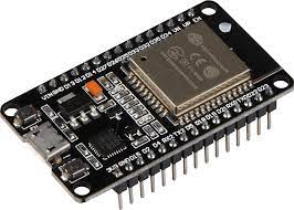
I wanted to upgrade my built-in car stereo with a bluetooth receiver, for streaming audio from my mobile phone. So I built one myself using the line-in port on my stereo that’s normally used for the CD-changer. In this case, I am using the ESP32 as a Bluetooth receiver and the PCM5102 as a DAC module for converting digital audio to an analog stereo signal. Advanced Audio Distribution Profile (A2DP) is a Bluetooth profile that allows hi-fi sound to be transmitted over a wireless Bluetooth connection. The connection between the ESP32 and the PCM5102 is based upon I2S (Inter-IC Sound) an electrical serial bus interface standard used for connecting digital audio devices together.
While ordering the ESP32’s I thought it was handy if there were already pins attached as it speeds up the building process (less soldering). But in this case, it might have been handier if no pins were soldered in the first place. I wanted to make a compact build (keeping the boards close together), as it needs to fit in my car (a Subaru Forrester). So I desoldered some pins from the ESP32 to make space for the PCM5102 board. I did this using a solder sucker (a.k.a. desoldering pump).
Steps for removing the pins:
- heat up your soldering iron,
- heat up the pins on your ESP32
- pump the solder away.
- bend the pin 90 degrees using a nose plyer
- while heating your pin from above, you can extract the pin using the nose plyer from below
- use heat to extract the pin, don’t use your strength (using force might damage your ESP32)

Now the necessary pins on the ESP32 are removed, you can focus on the PCM5102. First, we need to close the SCK bridge on the PCB by soldering a small blob on the PCM5102.
After that is done, we can connect the PCM5102 to the ESP32. If all is soldered well, it should look like this:
We need some code to program the ESP32 to make it all work. For that job, I am using the Arduino IDE to program the ESP32. So make sure you have the Arduino IDE and git installed on your machine. And before we can start, we also need to install the necessary libraries, so let’s go to your terminal window to install the libraries. You might want to copy and paste the following commands.
$ cd ~/Documents/Arduino/libraries
$ git clone https://github.com/pschatzmann/ESP32-A2DPNext, start up your Arduino IDE and select the proper ESP32 board in Arduino IDE (go to Tools, Board, Board Manager, ESP 32 Arduino, and select the proper lidevice). In my case, I choose the “ESP32 Wrover Module”. Now we can use the following code to program your ESP32.
#include "BluetoothA2DPSink.h" BluetoothA2DPSink a2dp_sink; void setup() < i2s_pin_config_t my_pin_config = < .bck_io_num = 4, .ws_io_num = 15, .data_out_num = 2, .data_in_num = I2S_PIN_NO_CHANGE >; a2dp_sink.set_pin_config(my_pin_config); a2dp_sink.start("MySubie"); > void loop()Now click on the upload button on top of the Arduino IDE. The code will be sent to your ESP32. When finished you should see the “Done uploading” message.
However, if you do get the error:
Failed to connect to ESP32: Timed out… Connecting…
- your cable is not connected or broken.
- you might not have selected the right board
- your ESP32 is not in flashing/uploading mode.
- Hold down the “BOOT” button on your ESP32 board
- When you see the “Connecting….” message in your Arduino IDE, release your finger from the “BOOT” button.
I really do love the small form factor of the ESP32 in combination with the PCM5102!
Suggestions for improving this article are welcome, please let me know and drop me a line.
Share this:
Related
Privacy & Cookies: This site uses cookies. By continuing to use this website, you agree to their use.
To find out more, including how to control cookies, see here: Cookie Policy


