ESP32 CAM PINOUT и внешняя Wi Fi антенна
Если посмотреть на фотку ESP32 CAM, может показаться, что там довольно много свободных GPIO для подключения датчиков, кнопок и прочих ништяков. но! не все так просто.
Разберем подробно для чего нужен каждый вывод данной платы:
5V питание +5V
3V3 — выход напряжения 3.3V
GND общий провод
IO4 — к этому выводу подключен встроенный сверхъяркий светодиод который может быть использован в качестве вспышки.
Чтобы помигать этим светодиодом можно написать такой код (не забудьте подключить внешний источник питания)
IO2, IO12, IO13, IO14, IO15 можно юзать как обычные цифровые пины (выход/вход/внутренние подтягивающие резисторы)
IO16 на нем висит второй аппаратный UART RX2, контроллера ESP32 (в среде Arduino IDE доступен через класс Serial2) на котором всегда будет логическая единица со всеми вытекающими отсюда последствиями:
- можно прицепить любой микроконтроллер и слать байты используя UART интерфейс
- как выход этот ПИН использовать не получиться
- использовать как вход можно, если прицепить туда кнопку, при нажатии которой данный ПИН будет подтягиваться к земле
IO0 необходим для заливки прошивки (смотрите мою предыдущую статью)
IOR, UOT порты аппаратного UART (в среде Arduino IDE доступны через класс Serial) используются для заливки прошивки в плату, гипотетически на них повесить что-то можно, а практически можно потерять возможность заливки скетчей и отладку через COM порт.
VCC — выход питания. Может выдавать либо 3.3V либо 5V в зависимости от установки перемычки (не совсем понятна ситуация когда это может вообще пригодиться. )
Для отладки кода на плате есть еще один светодиод расположенный на задней стороне платы:
Подключен он к GPIO33 и управляется инвертированной логикой.
Все становится значительно хуже если мы решим использовать в проекте SD карточку для сохранения фотографий
Если установить карту памяти и использовать библиотеку для сохранения фотографий на SD-карточку — свободных GPIO практически не остается. Впрочем эта проблема довольно легко обходится:
- написать WEB интерфейс и управлять функциями камеры через WEB браузер с любого устройства в домашней сети (если сети нет — настроить плату ESP32 как точку доступа)
- прикрутить на оставшийся свободным UART (GPIO IOR и UOT, любой другой микроконтроллер, придумать и написать протокол связи между платами и получить полноценную плату расширения с возможностью подключения любых внешних устройств, датчиков, дисплеев и.т.д. и.т.п.
Для эффективной работы c Wi-Fi в плате ESP32 предусмотрена возможность подключения внешней антенны.
Для переключения платы ESP32 CAM необходимо перепаять резистор (показан красной линий — или просто капнуть каплю припоя)
Подходящую антенну легко купить на али-экспресс вместе со «шнурком» с необходимым разъемом. (стоит около 100 рублей)
Я протестировал данное решение — скорость передачи фотографий даже с такой маленькой антенной значительно выросла. С использованием внутренней антенны полноценно поработать с платой ESP32 CAM не получится (объемы передаваемых данных тут значительно больше чем у часов или метеостанций).
Несколько слов про отсутствие USB разъема на борту.
Да, для программирования потребуется USB-UART конвертер, что не очень удобно — но с другой стороны это:
- меньшая цена
- сниженное энергопотребление (если вдруг придется делать фотосъемку в местах с отсутствием питания), на данной плате практически полностью отсутствует лишний обвес (светодиоды, конвертер и прочая хрень которая есть на платах Arduino), что значительно повышает срок возможности автономной работы.
Ну и последний совет:
Если надумаете покупать плату ESP32 CAM в Китае на Ali ищите оригинальную плату от Ai-Thinker. Звучит странно, но опасайтесь Китайских подделок из Китая ))). Оригинал будет стоить в районе 10$ — и покупать лучше в фирменных магазинах на Ali. (2 платы стоимостью 5$ после дня мучений у меня благополучно отправились в мусорную корзину и судя по информации с других технических форумов не только у меня). В отличии от плат Arduino ESP32 CAM Китайцы качественно подделывать пока еще не научились.
Для разработки софта делаю вот такой шилд
ESP32 Range Extender / Antenna Modification
When experimenting with ESP32 modules, especially the ESP32 CAMs, I wish I had a little more WIFI range reserve.
This could be achieved by adding an external antenna – but only a few modules are prepared for the connection of an external antenna. The resulting financial and mechanical outlay is also no longer negligible and may not be in good proportion to the range improvement actually required.
In the end, to keep it as simple but effective as possible, I added a half-wave antenna wire to the original onboard antenna of the ESP32 module.
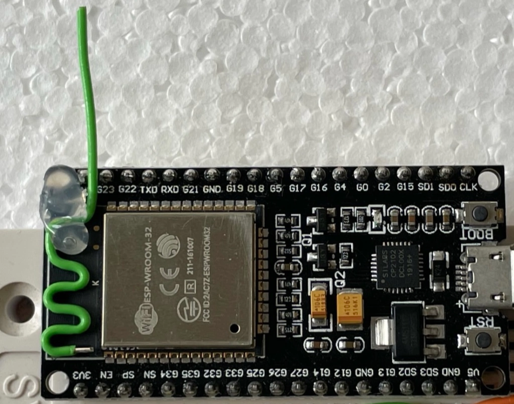
The original print antenna is a meander-shaped, inverted F antenna with 1/4 wavelength. It is a compromise between size, omnidirectional antenna pattern if possible, and power efficiency. I found very helpful sources of information about such kind of antennas at https://www.nxp.com/docs/en/application-note/AN2731.pdf and https://www.antenna-theory.com/antennas/aperture/ifa.php
My thought now was to increase the WIFI range of the module by a coupling between the on-board antenna and a newly added external half-wave antenna wire (AWG24 switch wire 0.5mm with 62mm 58mm length). However, no irreversible changes or soldering should become necessary. So I hot glued the additional antenna wire directly to the board.
Note that half of the additional antenna wire follows exactly the meandering outer shape of the printed F-antenna and is kept at a distance by the wire’s insulating material, while the other half is mounted “free”. This results in good inductive and capacitive coupling of the two antennas, which now work together. The best point for the hot glue in terms of high frequency is the (low impedance) center of the new half wave antenna just at the right corner of the ESP32 module.
Now it was time to prove my hopeful design in practice!
To show the effect, I mounted a modified module next to an unmodified one, so that both modules should have approximately the same reception conditions without influencing each other.
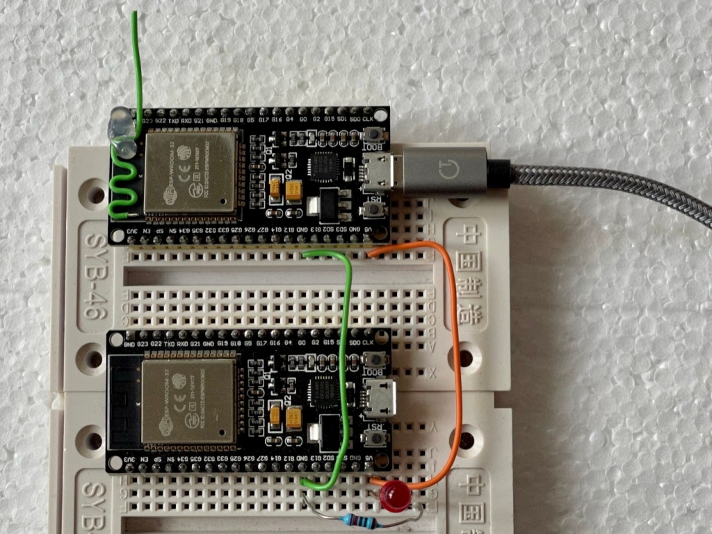
I wrote a few lines of ANNEX32 BASIC code that runs on both modules and displays the WIFI field strength measured by both devices in a Life Browser window. Module 1 (with additional antenna) logs its own WIFI RSSI and additionally requests a string with the logged RSSI from the second (unmodified) module. Thus this browser window always displays two sliding curves with the last 100 measurements = about 50 seconds.
For newcomers to ANNEX32 – a standalone BASIC interpreter/IDE that runs entirely in ESP32 and is only supported by Javascript in the browser when needed – here’s a link to the fabulous online manual.
I tested the effect of the additional antenna and recorded the WIFI strength under different conditions. Here I show only an abstract of my experiments and results.


It turns out that the signal is improved by at least 3 dB overall on the modified modules with an elongated non-angled antenna wire. Under very reflective conditions, I had an improvement of almost 10 dB.
However, the rough measurements also suggest that the better conditions find its counterparts in the nulls in the antenna pattern which are now somewhat more pronounced, as expected.
One of the reasons for the better gain is certainly the modified antenna pattern; another could be the strong coupling to an antenna that is not downsized, partially freestanding, and thus somewhat more effective.

Some things still to do …
I did some experiments with the free end of the antenna at a 90 degree angle up. This changed the resulting antenna pattern, which should certainly be investigated further to optimize the result. This variation can be helpful in certain mounting environments, such as when the module is sitting on a heavily populated PCB, then with a significantly more free-standing antenna.
I have not yet looked at optimizing the length of the half-wave wire, but have followed the best practice of 62 mm for 2.48GHz. Maybe it could be a little shorter, since it doesn’t just run free in the air and is not very massive. SEE UPDATE AT THE END!!
CONCLUSIONS :
Under given unfavorable conditions, this simple antenna modification cannot work miracles, but it can
– slightly increase the range of the ESP module or
– improve a given less stable WIFI connection.
This improvement inevitably comes with the disadvantage of more pronounced directivity. It works best when the module has a fixed location and when there is a possibility to adjust the orientation of the module’s antenna relative to the antenna of the AP.
A practical application: The described modification resulted in a much better signal and a very stable video connection with an ESP32 CAM module in a previously quite critical location.

This is the ANNEX32-BASIC-code used in the two ESP32-modules:
‘######## WIFI-GRAPH-LOGGER ####################################
‘ Allows to compair the two ESP-Modules which have different antennas
‘
‘ Displays a graphical logging of two WIFI-signals in dB
‘ — the OWN WIFI-connection to the WIFI access point
‘ — the WIFI-connection of a remote ESP32 to the same AP
‘
‘ TX = 1 => this ESP-Module returns the string with its
‘ WIFI-LOG-RESULT-STRING on request at http://MY_IP/msg?x=1
TX = 1
‘ RX = 1 => This ESP-Module regularly requests the WIFI-LOG-RESULT-STRING
‘ from remote module with http://REMOTE_IP/msg?x=1
RX = 0
REMOTE_IP$ = «192.168.0.141»
X_Num = 100 ‘Number of WIFI-MESSURES to display in the graph
WIFI_REMOTE$ = «»
onhtmlreload WEBPAGE
gosub WEBPAGE
if TX = 1 onurlmessage RETURN_WIFI_STRING
IF RX = 1 onwgetasync RECEIVE_REMOTE_STRING
timer0 500, LOG_MY_WIFI_CONNECTION
if RX = 1 timer1 1000, GET_REMOTE_WIFI_LOG_STRING
wait
‘###############################################################
LOG_MY_WIFI_CONNECTION:
w=0
for i = 1 to 50
w = wifi.rssi + w
next i
w=W/(i-1) ‘ Thanks for the hint Fernando !
WIFI_LOCAL$= trim$(WIFI_LOCAL$ + » » +str$(wifi.rssi,»%2.1f»))
c = word.count(WIFI_LOCAL$,» «)
p = instr(1, WIFI_LOCAL$, » «)
P = len(WIFI_LOCAL$) — p
If c > X_NUM then WIFI_LOCAL$ = right$(WIFI_LOCAL$, p )
‘wlog WIFI_LOCAL$ , c
jscall |traceme(0,»| + WIFI_LOCAL$ + |»);|
if WIFI_REMOTE$ <> «» jscall |traceme(1,»| + WIFI_REMOTE$ + |»);|
return
‘###############################################################
RETURN_WIFI_STRING:
URLMSGRETURN WIFI_LOCAL$
return
‘###############################################################
GET_REMOTE_WIFI_LOG_STRING:
wgetasync («http://» + REMOTE_IP$+ «/msg?x=1»)
return
‘###############################################################
RECEIVE_REMOTE_STRING:
WIFI_REMOTE$ = WGETRESULT$
return
‘###############################################################
WEBPAGE:
cls
‘ loads the library
jsexternal «/xy.min.js»
cnt = 0
a$ = «»
a$ = a$ + |
WIFI Graph for two ESP32-modules ..
|
a$ = a$ + |GREEN = WITH additional antenna
RED === with original antenna |
a$ = a$ + |
|
html a$
pause 500
‘ define che datasets
A$ = «»
A$ = A$ + |var datasets = [|
A$ = A$ + | <|
A$ = A$ + | lineColor : ‘rgba(20,100,100,1)’,|
A$ = A$ + | pointColor : ‘rgba(20,20,20,1)’,|
A$ = A$ + | pointStrokeColor : ‘#fff’,|
A$ = A$ + | data : []|
A$ = A$ + | >,|
A$ = A$ + | <|
A$ = A$ + | lineColor : ‘rgba(151,30,0,1)’,|
A$ = A$ + | pointColor : ‘rgba(151,80,0,1)’,|
A$ = A$ + | pointStrokeColor : ‘#fff’,|
A$ = A$ + | data : []|
A$ = A$ + | >|
A$ = A$ + |];|
A$ = A$ + |var ctx2 = document.getElementById(‘canvas1’).getContext(‘2d’);|
A$ = A$ + ||
A$ = A$ + |var xy = new Xy(ctx2,
A$ = A$ + ||
A$ = A$ + |function traceme(set, data)<|
A$ = A$ + | var s = data.split(» «);|
A$ = A$ + | for (var i=0; iA$ = A$ + | datasets[set].data[i] = [i, s[i]];|
A$ = A$ + | >|
A$ = A$ + | xy.draw(datasets);|
A$ = A$ + |>|
jscript a$
A$ = «» ‘ clean memory
return
For newcomers to ANNEX32 – a standalone BASIC interpreter/IDE that runs entirely in ESP32 and is only supported by Javascript in the browser when needed – here’s a link to the fabulous online manual.

EDIT: Optimizing the length of the halve-wave-antenna wire
I put a little work into optimizing the length of the wire.
After removing the insulation on a length of 15 mm and then shortening the wire by 6 mm, I added a variable extension made of a 10 mm*1 mm silver wire. For this, a piece of the heat shrink tubing served as a temporary slide holder.
This allowed me to easily match the wire length for the highest possible receive field strength. The actual influence of the dielectric, inductances and capacitances on the wire length was thus compensated. At the end I fixed the connection with very little solder.
The optimum length for the entire half-wave-antenna wire finally was 58mm. This is 4mm less than the old value and resulted in additional 1.5dB gain!
Want to read more about ESP32, its antenna, pifa etc? Here is listed what was helpful to me: