- Serial-to-WiFi Tutorial using ESP8266
- Usage
- Testing the module via FTDI (or a USB-to-Serial cable)
- Hardware setup
- Software and testing:
- Webserver example:
- Troubleshooting:
- Testing the module via a microcontroller
- Модуль Wi-Fi ESP8266 (ESP-01): подключение, прошивка и распиновка
- Видеообзор
- Общие сведения
- Работа с AT командами
- Подключение и настройка
- HardwareSerial
- SoftwareSerial
- HardwareSerial Mega
- Примеры работы
- Тестовая команда «AT»
- Настройка режима работы
Serial-to-WiFi Tutorial using ESP8266
The ESP8266 is a low cost Serial-to-WiFi module that interfaces nicely to any microcontroller. However, a word of caution — it is highly undocumented (primary reason for writing this document), and more importantly, it is frequently updated and not backward compatible. A good example is how newer versions use 9600 baud rate, while older versions (by old I’m referring to 2-3 months old modules) used 57600-115200 baud rates.
In general, the tutorial below will get you started. Once you are set up, you should learn more about the module’s protocol here: https://nurdspace.nl/ESP8266#AT_Commands
Usage
First, it is important to understand how the board works. The ESP8266 has a full TCP/UDP stack support. It can also be easily configured as a web server. The module accepts commands via a simple serial interface. It then responds back with the operation’s outcome (assuming everything is running correctly). Also, once the device is connected and is set to accept connections, it will send unsolicited messages whenever a new connection or a new request is issued.
Testing the module via FTDI (or a USB-to-Serial cable)
Before connecting the module to a microcontroller, it’s important to try it directly via a serial interface. An easy solution is to use a 3V3 FTDI cable. Note that the module is not designed for more than 3.6V, so a 3.3V power supply should be used — both for power and logic. The current batch of the FTDI cables deliver 5V in the supply rail even for the 3V3 version. Apparently, this is an error made by the manufacturer, so it might be corrected at some point.
Hardware setup
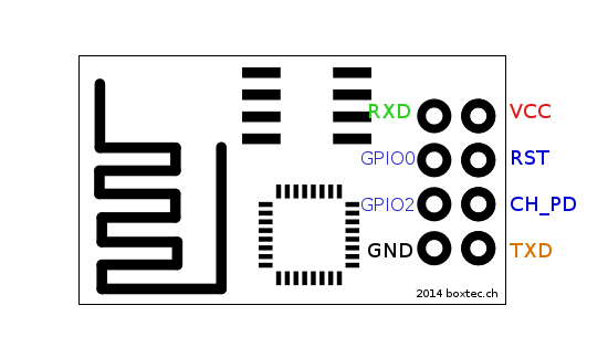
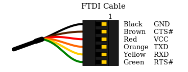
- Connect the RX/TX pins in a 3v3 FTDI cable to the TX/RX pins in the ESP module.
- Connect a 3v3 power supply to the VCC/GND pins. Note that it is possible to use an Arduino 3v3 supply for this.
- Connect the CH_PID pin to VCC as well.
- The rest of the pins should be floating. However, be prepared to occasionally ground the RST pin. This would help if the board is stuck on some command.
Software and testing:
- Clone this repository: https://github.com/guyz/pyesp8266
- Unzip and execute the following command: python esp8266test.py
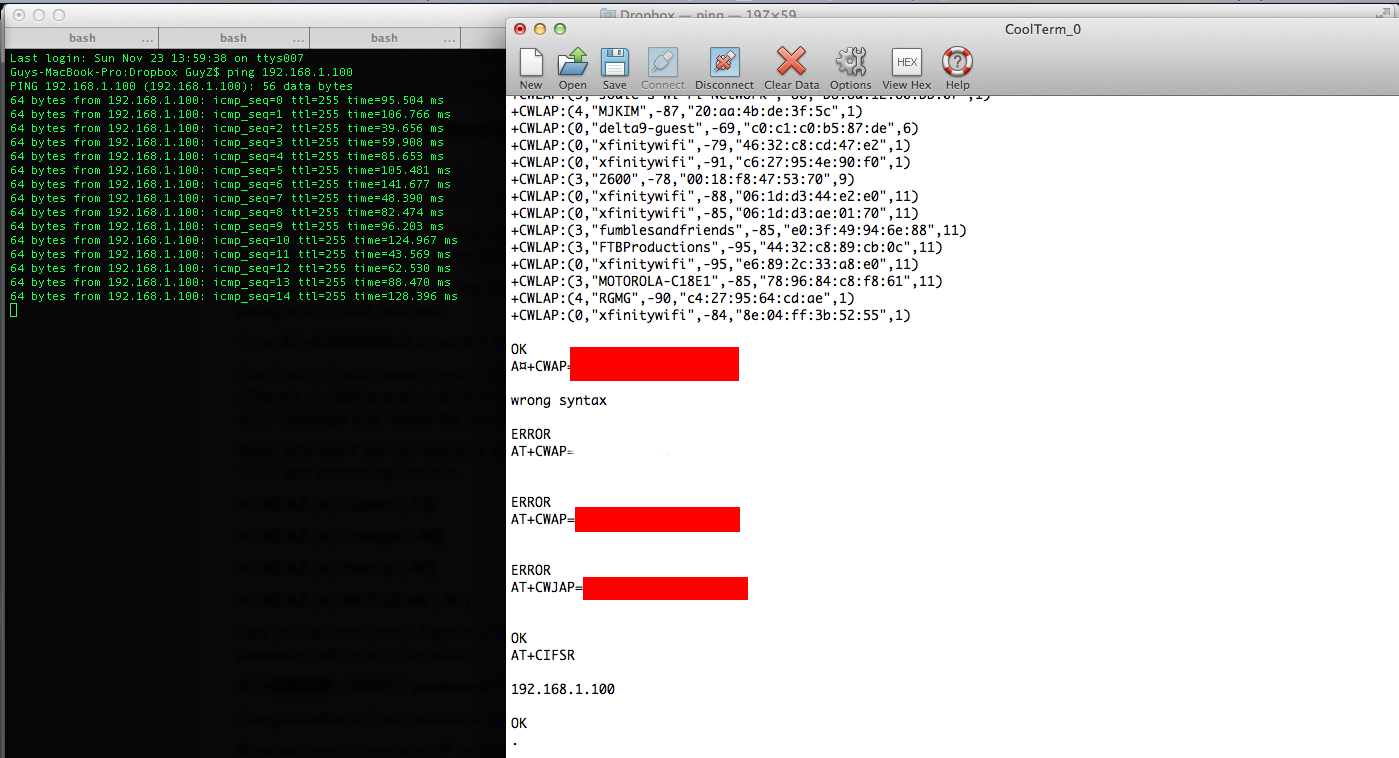
- You should see a bunch of commands going through, including a list of available APs. Eventually, you should see the IP address assigned to the module printed.
- ping the IP address obtained in (3). If that works (similar to the image below), then you got it working and can start doing cool stuff!
Webserver example:
Once you’ve successfully set up the device and confirmed that it can connect to a WiFi, you can try something more elaborate. the file esp8266server.py will go through the same flow as the test module, but it will also continue to setting up the device to accepting multiple connections:
send_cmd( "AT+CIPMUX=1" ) # multiple connection mode send_cmd( "AT+CIPSERVER=1,80" ) To run this module, issue the following command in the right directory:
Then, head to your browser and enter the following URL:
If everything works correctly, you should see the serial request being pushed through the serial interface. The python code would in turn serve a response back which will show on the browser. If you want to fiddle around with the response, look at this line in the code:
process_request("GOT IT! (" + str(datetime.datetime.now()) + ")") Troubleshooting:
If you encountered issues, check the following:
- Is the red LED on the module lit? If it isn’t, the board isn’t getting power.
- When trying to issue commands, do you see the blue LED on the module blinking? If not, check the RX/TX connections. If the LED is constantly lit, then one of the connections is wrong — probably RX/TX or one of the other pins.
- Are you seeing gibberish? You’re probably doing well, but try a different BAUD rate.
Testing the module via a microcontroller
Once you’ve got the module up and running with a direct serial connection, you can move on to plugging it into a microcontroller board. The steps are largely the same — you connect the RX/TX pins to the TX/RX pins of a microcontroller, or — if you’re using an Arduino like board — you can set up a SoftwareSerial interface and use any 2 digital pins for the communication.
As to powering up the device — while I have briefly tried and confirmed that a direct 5V supply could work, it is not recommended and your mileage may vary. There are multiple ways to regulate the voltage (e.g., http://rayshobby.net/?p=9734), or if you’re at the CBA lab — try using one of the larger 3.3V SOT223 voltage regulators, or a similar capable one.
If you’re using the Arduino IDE, you should check out these resources for some reference code:
The result should look something like this:

Модуль Wi-Fi ESP8266 (ESP-01): подключение, прошивка и распиновка
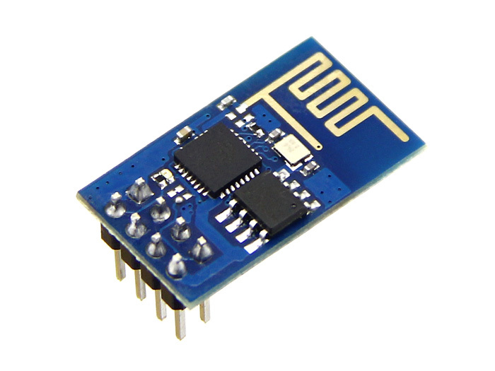
Модуль ESP-01 с чипом ESP8266 предназначен для связи устройства с беспроводными сетями по WiFi.
Видеообзор

Общие сведения
ESP-01 — плата-модуль WiFi на базе популярного чипсета ESP8266EX . На борту платы находится микросхема Flash-памяти объёмом 2 МБ, чип ESP8266EX, кварцевый резонатор, два индикаторных светодиода и миниатюрная антенна из дорожки на верхнем слое печатной платы в виде змейки. Flash-память необходима для хранения программного обеспечения. При каждом включении питания, ПО автоматически загружается в чип ESP8266EX.
По умолчанию модуль настроен на работу через «AT-команды». Управляющая плата посылает команды — Wi-Fi модуль выполняет соответствующую операцию.
Но внутри чипа ESP8266 прячется целый микроконтроллер, который является самодостаточным устройством. Прошивать модуль можно на разных языках программирования. Но обо всё по порядку.
Работа с AT командами
Подключение и настройка
В стандартной прошивке Wi-Fi модуль общается с управляющей платой через «AT-команды» по протоколу UART.
На всех платах Iskra и Arduino присутствует хотя бы один аппаратный UART — HardwareSerial. Если же по каким то причинам он занят другим устройством, можно воспользоваться программным UART — SoftwareSerial.
HardwareSerial
На управляющей плате Iskra JS и платах Arduino с микроконтроллером ATmega32U4 / ATSAMD21G18 данные по USB и общение через пины 0 и 1 осуществляется через два раздельных UART . Это даёт возможность подключить Wi-Fi модуль к аппаратному UART на пинах 0 и 1 .
Список поддерживаемых плат:
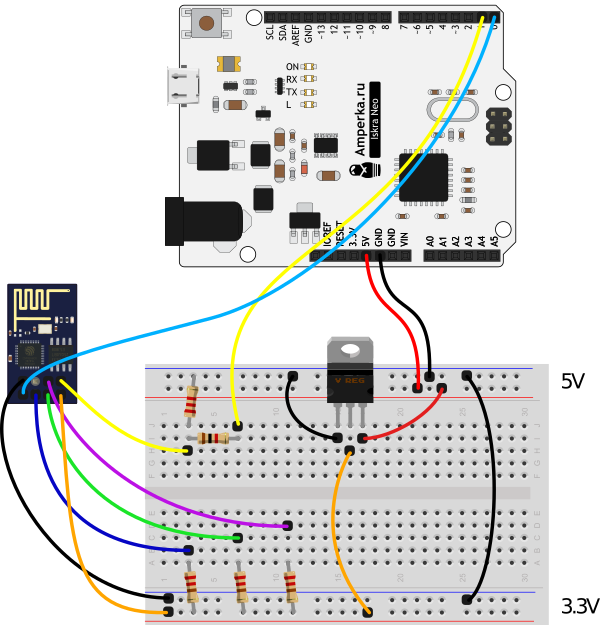
Для примера подключим модуль Wi-Fi к платформе Iskra Neo.
Прошейте управляющую платформу кодом ниже.
Код прошивки
// serial-порт к которому подключён Wi-Fi модуль #define WIFI_SERIAL Serial1 void setup() { // открываем последовательный порт для мониторинга действий в программе // и передаём скорость 9600 бод Serial.begin(9600); while (!Serial) { // ждём, пока не откроется монитор последовательного порта // для того, чтобы отследить все события в программе } Serial.print("Serial init OK\r\n"); // открываем Serial-соединение с Wi-Fi модулем на скорости 115200 бод WIFI_SERIAL.begin(115200); } void loop() { // если приходят данные из Wi-Fi модуля - отправим их в порт компьютера if (WIFI_SERIAL.available()) { Serial.write(WIFI_SERIAL.read()); } // если приходят данные из компьютера - отправим их в Wi-Fi модуль if (Serial.available()) { WIFI_SERIAL.write(Serial.read()); } }
SoftwareSerial
Некоторые платы Arduino, например Uno, прошиваются через пины 0 и 1 . Это означает невозможность использовать одновременно прошивку/отладку по USB и общение с Wi-Fi модулем. Решение проблемы — программный UART . Подключите пины TX и RX ESP-модуля к другим контактам управляющей платы и используйте библиотеку SoftwareSerial.
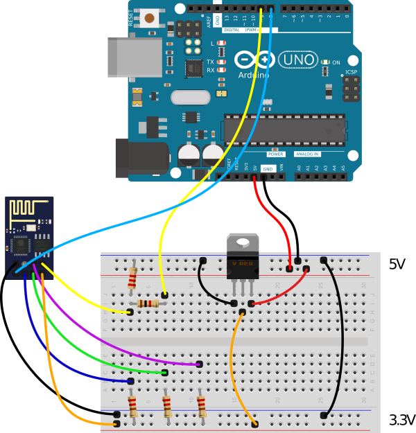
Для примера подключим управляющие пины Wi-Fi модуля TX и RX — на 8 и 9 контакты управляющей платы. Прошейте управляющую платформу кодом ниже.
Код прошивки
// библиотека для работы программного Serial #include // создаём объект для работы с программным Serial // и передаём ему пины TX и RX SoftwareSerial mySerial(8, 9); // serial-порт к которому подключён Wi-Fi модуль #define WIFI_SERIAL mySerial void setup() { // открываем последовательный порт для мониторинга действий в программе // и передаём скорость 9600 бод Serial.begin(9600); while (!Serial) { // ждём, пока не откроется монитор последовательного порта // для того, чтобы отследить все события в программе } Serial.print("Serial init OK\r\n"); // открываем Serial-соединение с Wi-Fi модулем на скорости 115200 бод WIFI_SERIAL.begin(115200); } void loop() { // если приходят данные из Wi-Fi модуля - отправим их в порт компьютера if (WIFI_SERIAL.available()) { Serial.write(WIFI_SERIAL.read()); } // если приходят данные из компьютера - отправим их в Wi-Fi модуль if (Serial.available()) { WIFI_SERIAL.write(Serial.read()); } }
HardwareSerial Mega
На платах форм-фактора Arduino Mega 2560 аппаратный UART, который отвечает за передачу данных через пины 1 и 0 , отвечает также за передачу по USB. Это означает невозможность использовать одновременно UART для коммуникации с Wi-Fi модулем и отладки по USB.
Но на платах такого форм-фактора есть ещё дополнительно три аппаратных UART:
Список поддерживаемых плат:
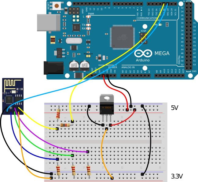
Подключите Wi-Fi модуль к объекту Serial1 на пины 18 и 19 на примере платы Mega 2560 Прошейте управляющую платформу кодом ниже.
Код прошивки
// serial-порт к которому подключён Wi-Fi модуль #define WIFI_SERIAL Serial1 void setup() { // открываем последовательный порт для мониторинга действий в программе // и передаём скорость 9600 бод Serial.begin(9600); while (!Serial) { // ждём, пока не откроется монитор последовательного порта // для того, чтобы отследить все события в программе } Serial.print("Serial init OK\r\n"); // открываем Serial-соединение с Wi-Fi модулем на скорости 115200 бод WIFI_SERIAL.begin(115200); } void loop() { // если приходят данные из Wi-Fi модуля - отправим их в порт компьютера if (WIFI_SERIAL.available()) { Serial.write(WIFI_SERIAL.read()); } // если приходят данные из компьютера - отправим их в Wi-Fi модуль if (Serial.available()) { WIFI_SERIAL.write(Serial.read()); } }
Примеры работы
Рассмотрим несколько примеров по работе с «AT-командами»
Тестовая команда «AT»
Откройте монитор порта. Настройте скорость соединения — 9600 бод. Конец строки — NL & CR . Введите команду AT и нажмите «Отправить». Это — базовая команда для проверки работы Wi-Fi модуля. 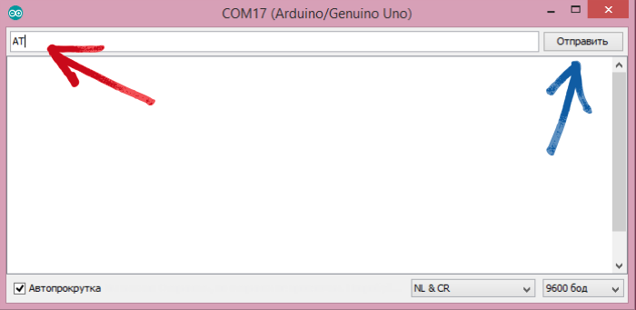 В ответ получим «OK»:
 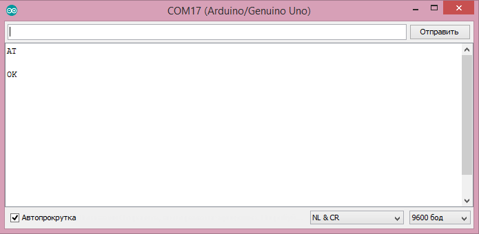 Если ответа нет или появляются непонятные символы — проверьте правильность подключения и настройки скорости обмена данными.
Настройка режима работы
Wi-Fi модуль умеет работать в трёх режимах: