- Ethernet to wifi esp
- Re: Ethernet to WiFi example question
- Re: Ethernet to WiFi example question
- Communication between two ESP32
- Communication between two ESP32 — Overview
- Communication between two ESP32 via Ethernet/WiFi
- Example Application
- Self-defined Protocol
- Wiring Diagram
- ESP32 Code for ESP32 #1
- ESP32 Code for ESP32 #2
- Quick Instructions
- Video Tutorial
- How to connect two ESP32 via Internet
- Saved searches
- Use saved searches to filter your results more quickly
- License
- m3y54m/esp32-ethernet-to-wifi-ap
- Name already in use
- Sign In Required
- Launching GitHub Desktop
- Launching GitHub Desktop
- Launching Xcode
- Launching Visual Studio Code
- Latest commit
- Git stats
- Files
- README.md
- Saved searches
- Use saved searches to filter your results more quickly
- dokmic/eth2wlan
- Name already in use
- Sign In Required
- Launching GitHub Desktop
- Launching GitHub Desktop
- Launching Xcode
- Launching Visual Studio Code
- Latest commit
- Git stats
- Files
- README.md
- About
Ethernet to wifi esp
Post by kluverp » Mon Dec 10, 2018 6:53 am
Hope someone can provide me an answer to this.
I have successfully applied the Ethernet-to-WiFi example. (Great example BTW).
But now I have the following question:
Is it possible to have the Ethernet work stand-alone next to the WiFi forwarding?
To explain more: the example pipes the WiFi connection to the Ethernet port. This works, but the Ethernet port itself no longer receives any IP address.
What I want to accomplish is is:
1) Users can connect to WiFi AP, and all communication goes over Ethernet (works).
2) Have the Ethernet connection still available to ESP, so the ESP can make use of the Ethernet to send data to the web. (no longer works, since Ethernet no longer has any IP assigned).
Is it possible? I want to keep using the Ethernet on the ESP board for data communication, AND have it work as an WiFi AP.
Re: Ethernet to WiFi example question
Post by ESP_@In逍遥子 » Mon May 06, 2019 2:45 am
Ritesh Posts: 1346 Joined: Tue Sep 06, 2016 9:37 am Location: India Contact:
Re: Ethernet to WiFi example question
Post by Ritesh » Wed Jun 12, 2019 8:21 am
Hope someone can provide me an answer to this.
I have successfully applied the Ethernet-to-WiFi example. (Great example BTW).
But now I have the following question:
Is it possible to have the Ethernet work stand-alone next to the WiFi forwarding?
To explain more: the example pipes the WiFi connection to the Ethernet port. This works, but the Ethernet port itself no longer receives any IP address.
What I want to accomplish is is:
1) Users can connect to WiFi AP, and all communication goes over Ethernet (works).
2) Have the Ethernet connection still available to ESP, so the ESP can make use of the Ethernet to send data to the web. (no longer works, since Ethernet no longer has any IP assigned).
Is it possible? I want to keep using the Ethernet on the ESP board for data communication, AND have it work as an WiFi AP.
But, That can be possible from ESP32 IDF example i believe as you can register Ethernet Interface into TCP IP Adapter.
Communication between two ESP32

Disclosure: some of these links are affiliate links. We may earn a commission on your purchase at no extra cost to you. We appreciate it.
Communication between two ESP32 — Overview
There are many ways to make ESP32 #1 communicate with ESP32 #2. Depending on the distance, we can choose one of the below ways:
| Methods | Distance |
|---|---|
| SPI | very short |
| I2C | very short |
| UART (TTL) | very short |
| UART (RS-232/485/422) | short |
| Bluetooth | short |
| LoRa | long |
| Ethernet/WiFi | unlimited (*) |
If we does not connect both ESP32 to the Internet, but we connect them to the same LAN network, the communication distance is restricted within the LAN network.
This tutorial is going to use Ethernet/WiFi for communication between two ESP32.
Communication between two ESP32 via Ethernet/WiFi
Two ESP32 can communicate with each other via Ethernet/WiFi if:
There are two ways that two ESP32 can communicate to each other.
Two ESP32 communicate with each other directly: one ESP32 is a TCP client, the other is a TCP server.
Two ESP32 communicate with each other indirectly via a centralized server (e.g. MQTT server): both ESP32 are TCP clients.
It needs an application protocol that two ESP32 uses to communicate to each other. For example:
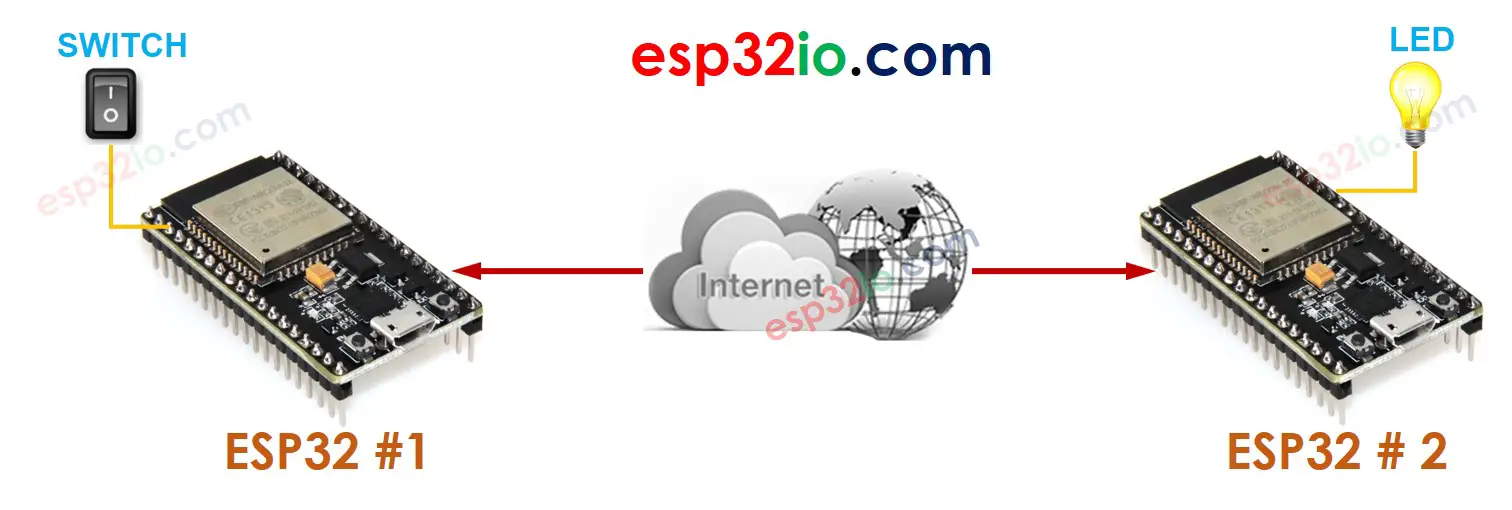
Example Application
Let’s realize the following application: A button/switch connected to ESP32 #1 controls an LED connected to ESP32 #2 via Ethernet/WiFi.
To make it simple, This tutorial will use a self-defined protocol (Defined by us, no standard)
Self-defined Protocol
We define a simple protocol as follows:
TCP server: listens to a TCP connection request from ESP32 #1. If there is a TCP request, it accepts and the connection is created.
Wiring Diagram
It needs touse a resistor for LED if it does not have a built-in resistor. We have dedicated tutorials for button and LED. You can learn more about them in:
ESP32 Code for ESP32 #1
ESP32 Code for ESP32 #2
Quick Instructions
Open another Arduino IDE window (called Arduino IDE #2) by clicking on Arduino IDE icon on your PC (important! (**) )
ESP32 #2: TCP SERVER + AN LED TCP Server IP address: 192.168.0.2 -> Please update the serverAddress in ESP32 #1 code
ESP32 #1: TCP CLIENT + A BUTTON/SWITCH ESP32 #1: Connected to TCP server ESP32 #1: — The button is pressed, sent command: 1 ESP32 #1: — The button is released, sent command: 0 ESP32 #1: — The button is pressed, sent command: 1 ESP32 #1: — The button is released, sent command: 0 ESP32 #1: — The button is pressed, sent command: 1 ESP32 #1: — The button is released, sent command: 0
ESP32 #2: TCP SERVER + AN LED ESP32 #2: TCP Server IP address: 192.168.0.2 ESP32 #2: -> Please update the serverAddress in ESP32 #1 code ESP32 #2: — Received command: 1 ESP32 #2: — Received command: 0 ESP32 #2: — Received command: 1 ESP32 #2: — Received command: 0 ESP32 #2: — Received command: 1 ESP32 #2: — Received command: 0
(**): If you open Arduino IDE #2 window via «File» → «New» or «Open» from Arduino IDE #2 window, you will NOT be able to open two Serial Monitors for two ESP32 in the same PC at the same time.
There is an alternative to this self-defined protocol. It is the Modbus TCP. The Modbus protocol is standardized, it has many advantages over the self-defined protocol. See more in ESP32 — Modbus tutorial
Video Tutorial
Making video is a time-consuming work. If the video tutorial is necessary for your learning, please let us know by subscribing to our YouTube channel , If the demand for video is high, we will make the video tutorial.
How to connect two ESP32 via Internet
Please note that this tutorial is under development. We will post on our Facebook Page when the tutorial is complete. Like it to get updated.
Saved searches
Use saved searches to filter your results more quickly
You signed in with another tab or window. Reload to refresh your session. You signed out in another tab or window. Reload to refresh your session. You switched accounts on another tab or window. Reload to refresh your session.
Create WiFi Access Point from Ethernet using ESP32 and LAN8720
License
m3y54m/esp32-ethernet-to-wifi-ap
This commit does not belong to any branch on this repository, and may belong to a fork outside of the repository.
Name already in use
A tag already exists with the provided branch name. Many Git commands accept both tag and branch names, so creating this branch may cause unexpected behavior. Are you sure you want to create this branch?
Sign In Required
Please sign in to use Codespaces.
Launching GitHub Desktop
If nothing happens, download GitHub Desktop and try again.
Launching GitHub Desktop
If nothing happens, download GitHub Desktop and try again.
Launching Xcode
If nothing happens, download Xcode and try again.
Launching Visual Studio Code
Your codespace will open once ready.
There was a problem preparing your codespace, please try again.
Latest commit
Git stats
Files
Failed to load latest commit information.
README.md
Create WiFi Access Point from Ethernet using ESP32 and LAN8720

- RMII PHY wiring is fixed and can not be changed through either IOMUX or GPIO Matrix. By default, they’re connected as follows:
- SMI (Serial Management Interface) wiring is not fixed. You may need to changed it according to your board schematic. By default they’re connected as follows:
Because GPIO0 is a strapping pin for entering UART flashing mode on reset, care must be taken when also using this pin as EMAC_TX_CLK. If the clock output from the PHY is oscillating during reset, the ESP32 may randomly enter UART flashing mode.
One solution is to use an additional GPIO as a «power pin», which either powers the PHY on/off or enables/disables the PHY’s own oscillator. This prevents the clock signal from being active during a system reset. For this configuration to work, GPIO0 also needs a pullup resistor and the «power pin» GPIO will need a pulldown resistor — as appropriate in order to keep the PHY clock disabled when the ESP32 is in reset.

See the example source code to see how the «power pin» GPIO can be managed in software.
The example defaults to using GPIO 5 for this function, but it can be overriden. On Espressif’s Ethernet development board, GPIO 17 is the power pin used to enable/disable the PHY oscillator.
| GPIO | Enable PHY Oscillator | Note |
|---|---|---|
| GPIO5 | PHY_OSC_ENABLE | Pull-down using a 10k resistor |
Saved searches
Use saved searches to filter your results more quickly
You signed in with another tab or window. Reload to refresh your session. You signed out in another tab or window. Reload to refresh your session. You switched accounts on another tab or window. Reload to refresh your session.
ESP32 Ethernet to WLAN Bridge
dokmic/eth2wlan
This commit does not belong to any branch on this repository, and may belong to a fork outside of the repository.
Name already in use
A tag already exists with the provided branch name. Many Git commands accept both tag and branch names, so creating this branch may cause unexpected behavior. Are you sure you want to create this branch?
Sign In Required
Please sign in to use Codespaces.
Launching GitHub Desktop
If nothing happens, download GitHub Desktop and try again.
Launching GitHub Desktop
If nothing happens, download GitHub Desktop and try again.
Launching Xcode
If nothing happens, download Xcode and try again.
Launching Visual Studio Code
Your codespace will open once ready.
There was a problem preparing your codespace, please try again.
Latest commit
Git stats
Files
Failed to load latest commit information.
README.md
The project enables ethernet to Wi-Fi data forwarding function (Ethernet to Wi-Fi bridge). It supports both station and access point mode.
The similarities on MAC layer between Ethernet and Wi-Fi make it easy to forward packets from Ethernet to Wi-Fi and vice versa. This example illustrates how to implement a simple «router» which only supports forwarding packets between Ethernet port and Wi-Fi interface.
In this example, ESP32 works like a bridge between Ethernet and Wi-Fi, and it won’t perform any actions on Layer3 and higher layer, which means there’s no need to initialize the TCP/IP stack.
To run this example, it’s recommended that you have an official ESP32 Ethernet development board — ESP32-Ethernet-Kit. This example should also work for 3rd party ESP32 board as long as it’s integrated with a supported Ethernet PHY chip. Up until now, ESP-IDF supports up to four Ethernet PHY: LAN8720 , IP101 , DP83848 and RTL8201 , additional PHY drivers should be implemented by users themselves.
Besides that, esp_eth component can drive third-party Ethernet module which integrates MAC and PHY and provides common communication interface (e.g. SPI, USB, etc). This example will take the DM9051 as an example, illustrating how to install the Ethernet driver in the same manner.
See here the common pin assignments for Ethernet examples.
docker-compose run --rm idf idf.py menuconfig
In addition to the common configurations, you might need to update the default values of following configuration:
In the Ethernet to WLAN Configuration menu:
Build the project and flash it to the board, then run monitor tool to view serial output:
docker-compose run --rm idf idf.py build flash monitor
To exit the serial monitor, type Ctrl-] .
See the Getting Started Guide for full steps to configure and use ESP-IDF to build projects.
See here the common troubleshooting for Ethernet examples.
- If you got error message like WiFi send packet failed when running the example, you may need to enlarge the value of FLOW_CONTROL_WIFI_SEND_DELAY_MS in «ethernet_example_main.c», because Ethernet process packets faster than Wi-Fi on ESP32.
- If you got error message like send flow control message failed or timeout when running the example, you may need to enlarge the value of FLOW_CONTROL_QUEUE_LENGTH in «ethernet_example_main».
About
ESP32 Ethernet to WLAN Bridge