Saved searches
Use saved searches to filter your results more quickly
You signed in with another tab or window. Reload to refresh your session. You signed out in another tab or window. Reload to refresh your session. You switched accounts on another tab or window. Reload to refresh your session.
Flipper Zero
- Home
- About
- FAQ
- Marauder Versions
- Troubleshooting
- Getting Started
- Arduino IDE Setup
- DIY Platforms
- ESP32 Marauder Kit
- Flipper Zero
- Installing Firmware via OTA
- Installing Firmware From Source
- Antenna Options
- IC Connections
- Battery
- 3D Printed Enclosure
- External Antenna Mod
- Commands
- attack
- channel
- clearlist
- help
- led
- list
- reboot
- scanap
- scansta
- select
- settings
- sigmon
- sniffraw
- sniffbeacon
- sniffdeauth
- sniffesp
- sniffpmkid
- sniffpwn
- ssid
- stopscan
- update
- Random Beacon Spam workflow
- List Beacon Spam workflow
- AP Clone spam workflow
- Deauthentication Attack workflow
- Probe Request Attack workflow
- Targeted Active PMKID Sniff workflow
- Signal Monitor Workflow
- WiFi
- WiFi Sniffers
- Probe Request Sniff
- Beacon Sniff
- Deauth Sniff
- Packet Monitor
- EAPOL PMKID Scan
- Detect Pwnagotchi
- Detect Espressif
- Scan APs
- Raw Sniff
- Scan Stations
- Signal Monitor
- Beacon Spam List
- Beacon Spam Random
- Rick Roll Beacon
- Probe Request Flood
- Deauth Flood
- AP Clone Spam
- Join WiFi
- Shutdown WiFi
- Add SSID
- Generate SSIDs
- Clear SSIDs
- Clear APs
- Select APs
- Select Stations
- Bluetooth Sniffers
- Bluetooth Sniffer
- Detect Card Skimmers
- Shutdown BLE
- Test BadUSB
- Run Ducky Script
- Draw
- Update Firmware
- Web Update
- SD Update
- ESP8266 Update
Clone this wiki locally
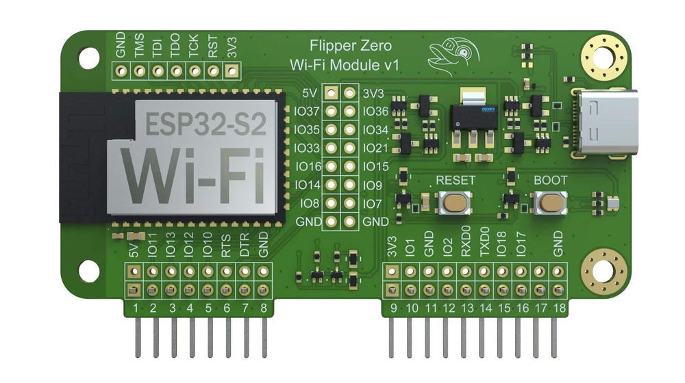
Flipper Zero WiFi Dev Board with Marauder

If at any moment you need further guidance, consider joining the discord server.
The Flipper Zero has the option to attach different peripherals to it’s GPIO headers. One such option is the ESP32-S2 Development Board which provides the Flipper Zero with the hardware required for WiFi capabilities. The Marauder firmware can be installed on the ESP32-S2 either via prebuilt firmware binary uploaded over-the-air(OTA) or via configured source build and upload. For either process, it will be assumed the connection between your PC and your WiFi dev board is «direct» i.e. you are not using the Flipper Zero USB-to-UART bridge. Once the install is complete however, you will be required to use the Flipper Zero USB-to-UART bridge.
It is recommended to use the Flasher Script option if you choose «Blue Pill» as this is the quickest and most direct method for installing the Marauder firmware on your WiFi Dev Board
If you do not currently own a 3D printer and would like to purchase an enclosure for your WiFi Dev Board, I am currently selling them on Tindie with multiple color and material options. If you are interested, check out the shop here.


Blue pill Red Pill Really easy. Nothing to change, but you don’t get any customization (which is fine). This pill is the size of a large pumpkin and it goes in your ass. Install libraries, build from source, know everything Spacehuhn Web Installer, FZ Marauder Flasher, FZEasyMarauderFlash, or Marauder OTA Build from source Once you have installed the firmware, be sure to check what to do next.
This video by Lab 401 will provide instructions for using the flasher script. This is the quickest way to get Marauder running on your device
Once you install the Marauder firmware on the WiFi dev board, you can connect the dev board to the Flipper Zero GPIO header and connect the flipper to your PC or Android phone via USB cable.
On the Flipper Zero, navigate to GPIO > USB-UART Bridge . I keep my Bridge configured to use USB channel 0If you don’t have a dev board, you can learn how to make one here.
If you are having issues with your Marauder installation either with the install process or with the firmware usage, be sure to check if your issue has already been solved in FAQ. If not, feel free to join my Discord to request help from the community or submit an issue
Marauder can be used via its command-line interface supplemented by the Flipper Zero USB-to-UART bridge and a PC/Laptop. The goal is to eventually get the Flipper Zero to offer a bluetooth connection to facilitate a Serial-over-Bluetooth bridge to the WiFi Dev Board so everything can be done over mobile phone.
For tethered use, follow these steps.- Connect your dev board to your flipper zero and power it on
- Connect your flipper zero to your PC/Mobile phone via USB-C
- On your flipper, open the USB-UART Bridge via the GPIO menu
- Configure the bridge to use USB channel 0 with baud 115200
- On your PC or mobile device, open a serial connection to the Flipper Zero with baud 115200
- Be sure to check what COM port your flipper zero is on so you know what to connect to
If you would like to use the Flipper Zero and it’s WiFi dev board flashed with Marauder as a standalone unit without a PC or mobile phone attached, install any of the following 3rd party Flipper Zero firmwares on your device. They come prebuilt with the WiFi Marauder fap created by 0xchocolate.
Note: We now offer a dedicated SD adapter board for a clean install on the Flipper Zero WiFi Dev Board. No wires are necessary.
A MicroSD card can be attached to the Flipper Zero WiFi Dev Board SPI via a MicroSD Breakout. Attaching a microSD card to the Flipper Zero WiFi Dev Board will allow the Marauder firmware to save captured WiFi traffic to storage in the form of PCAP files to be exported for analysis later. If you install this mod, DO NOT use the flipper_sd_serial.bin to update your WiFi Dev Board. Refer to the following table for the required solder connectionsMicroSD Breakout Flipper Zero WiFi Dev Board VCC 3V3 GND GND DI (MOSI) IO35 DO (MISO) IO37 SCK IO36 CS IO10 Once all of the solder connections have been made, a piece of double-sided tape can be used to fix the MicroSD Breakout Board to the back of the WiFi Development Board.
If you are looking to support me and my pursuit of shitty projects, consider heading over to my Patreon. It aint much and it’s not very big around, but it’ll get the job done.
The following video describes and demonstrates the installation and usage of the Marauder firmware on the Flipper Zero WiFi Dev Board.
If you’re trying to figure out what to do now that you have Marauder installed on your Flipper Zero, consider reading Commandline for how to use the Marauder command line interface, and Workflow Examples to understand how to use some of the commands in a practical way.
Wi-Fi Developer Board
Wi-Fi-enabled Developer Board brings debugging and firmware update capabilities to your Flipper Zero. The Developer Board is based on the ESP32-S2 MCU with custom firmware incorporating Black Magic Debug and CMSIS-DAP, and is built with ESP-IDF. It can flash and debug various microprocessors and microcontrollers (including the one used in your Flipper Zero) via Wi-Fi or USB cable.
The Developer Board provides a debug interface, allowing developers to halt program execution, set breakpoints, inspect variables and memory, and step through code execution. This Developer Board can also act as a USB-UART adapter.
div class="info flipper-callout"> div class="callout-header">div> Out of the box, the Developer Board firmware does not contain Wi-Fi network analysis and penetration testing features. However, they can be implemented additionally. div>Hardware
The Developer Board is equipped with an ESP32-S2-WROVER module, which includes built-in Wi-Fi capabilities. It also offers GPIO pins for easy connectivity to various targets. Additionally, the Developer Board features a USB Type-C connector for data transfer and power supply. For user interaction, the Developer Board has tactile switches.
To learn more about the Wi-Fi Developer Board hardware, visit Schematics . For additional information regarding Flipper Zero GPIO pins, visit GPIO & modules .
Debugging process overview
div class="info flipper-callout"> div class="callout-header">div> Update your Wi-Fi Developer Board before using it. For more information, visit a href="https://docs.flipperzero.one/development/hardware/wifi-debugger-module/update" onclick="next.router.push('https://docs.flipperzero.one/development/hardware/wifi-debugger-module/update')">u>Wi-Fi module firmware updateu>. div>The debugging capability of the Wi-Fi Developer Board is based on the GNU Debugger (GDB), which allows developers to examine and manipulate the internal state of a running program on the target, set breakpoints, step through code execution, inspect variables and memory, and analyze program flow.
The Developer Board acts as the GDB server , which provides a bridge between the GDB client running on a host computer and the target microcontroller (your Flipper Zero) . The debugging process is controlled by the user on a computer connected to the module via Wi-Fi or USB cable:
Via USB: The Developer Board is connected to the computer using a USB Type-C cable, and the system recognizes the device as a COM port.
V ia Wi-Fi: The Developer Board broadcasts its own Wi-Fi network to which your computer can be connected. After connecting to the network, you can set up the connection to an existing Wi-Fi network.
Data exchange between the Wi-Fi Developer Board and your Flipper Zero is conducted via the Serial Wire Debug interface. The following GPIO pins serve this purpose:
Additionally, explore the following pages dedicated to the Wi-Fi Developer Board:
Модуль Wi-Fi Devboard для Flipper Zero
Товары из офиса нельзя заказать через интернет или забронировать. Можно только прийти, схватить и бежать. Доступное количество актуально на момент загрузки страницы.
Офис находится в 3 минутах ходьбы от м. Парк культуры по адресу: ул. Тимура Фрунзе, 8/5.
Товары из магазина-мастерской нельзя заказать через интернет или забронировать. Можно только прийти, схватить и бежать. Доступное количество актуально на момент загрузки страницы.
Магазин-мастерская находится в трёх минутах пешком от метро Лиговский Проспект, на территории пространства «Лофт Проект Этажи», по адресу Лиговский проспект 74Д.
Подарите своему кибердельфину способность проводить аппаратный дебаг, общаясь через беспроводное соединение Wi-Fi!
Специальный модуль для Flipper Zero построен на чипе ESP32-S2 и предназначен для работы в режиме отладчика Black Magic через GDB (GNU DeBugger).
Особенности
- Удобное подключение к Flipper Zero через GPIO и дополнительные контакты ввода-вывода.
- Возможность обновления прошивки Flipper Zero по воздуху.
- Продвинутый аппаратный дебаг по USB/Wi-Fi с помощью открытого проекта Black Magic Probe.
- Возможность интернет-соединения и теста Wi-Fi-сетей на проникновение (при условии дополнительной разработки).
Комплектация
Характеристики
- Совместимость: Flipper Zero
- Однокристальная система (SoC): Espressif ESP32-S2
- Вычислительное ядро: Tensilica Xtensa LX7 (32 бита)
- Тактовая частота: до 240 МГц
- SRAM-память: 320 КБ
- ROM-память: 128 КБ
- Flash-память: 4 МБ (SPI)
- Беспроводная связь: Wi-Fi 802.11 b/g/n
- Частотный диапазон связи: 2,4 ГГц
- Скорость передачи данных: до 150 Мбит/с
Ресурсы
Наверняка понадобятся
Flipper Zero Портативный гаджет-мультитул для гиков на Open Source-платформе с ЖК-дисплеем 1,4″ и кучей интерфейсов
- WiFi Sniffers

/i/663561/products/2022-06-22T17%3A49%3A07.471Z-IMG_2245.JPG?1655894975)
/i/663561/products/2022-06-22T17%3A49%3A07.471Z-IMG_2242.JPG?1655894975)
/i/663561/products/2022-08-23T17%3A05%3A36.894Z-IMG_5955%20-%20Copy.jpg?1661249267)