- HC-05 pinout, specifications, datasheet and HC05 Arduino connection
- Introduction to HC-05 Bluetooth Module
- Working of HC-05 Bluetooth Module:
- Command Mode:
- Data Mode:
- HC-05 Breakout Board Pinout:
- Applications of HC-05 Bluetooth module:
- Arduino — Bluetooth
- Hardware Required
- About HC-05 Bluetooth Module
- Pinout
- How It Works
- HC-05 Default Settings
- About Bluetooth Serial Monitor App
- Wiring Diagram
- How To Program For Bluetooth
- Arduino sends data to Bluetooth App on Smartphone
- Quick Steps
- Bluetooth App Send data To Arduino
- Quick Steps
- Arduino Code — Control LED with smartphone App via Bluetooth
- Arduino Code — Control Servo Motor with smartphone App via Bluetooth
- Video Tutorial
- Pin Description
- Package Information
- HC-05
- Hardware
- HC- 05 vs HC-06
- Connecting HC-05 with Microcontroller
- Applications
- Modes of Operation
- Download here
HC-05 pinout, specifications, datasheet and HC05 Arduino connection
Introduction to HC-05 Bluetooth Module
The HC-05 is very easy to use Bluetooth to serial converter. HC-05 connects microcontrollers (like Arduino) to other Bluetooth enabled devices. This allows the devices to communicate wirelessly with each other.
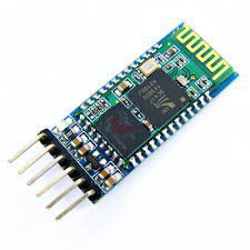
HC-05 is a Bluetooth SPP (Serial Port Protocol) module designed for wireless communication. It can also be operated as a master or slave configuration.
Working of HC-05 Bluetooth Module:
The HC-05 Bluetooth Module can be used in two modes of operation: Command Mode and Data Mode.
Command Mode:
In Command Mode, we can communicate with the Bluetooth module through AT Commands to configure various settings and parameters of the Module. This includes the firmware information, changing Baud Rate, changing module name, etc. We can also use it to set HC-05 as a master or slave. To select either of the modes, we need to activate the Command Mode and sent the correct AT Commands. Baud rate is 38400bps in command mode .
Data Mode:
In this mode, the module is used for communicating with other Bluetooth devices i.e. data transfer happens in this mode. Exchange of data between devices. Baud rate is 9600bps in data mode.
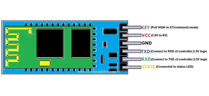
HC-05 Breakout Board Pinout:
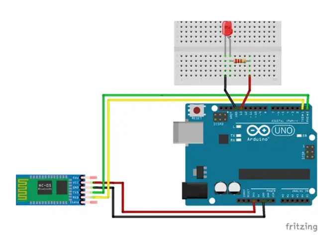
- Connect and a LED to an Arduino board with the help of jumper wires.
- Connect the Bluetooth module (HC-05) to the Arduino with the help of jumper wires. Except for the first and the last pin, all other pins need to be connected to the Arduino.
- Ground of HC-05 to Ground of Arduino.
- Power of HC-05 to 3.3V of Arduino.
- Tx of HC-05 to Rx of Arduino.
- Rx of HC-05 to Tx of Arduino.
Applications of HC-05 Bluetooth module:
- Computer and peripheral devices
- GPS receiver
- Industrial control
- MCU projects
Arduino — Bluetooth
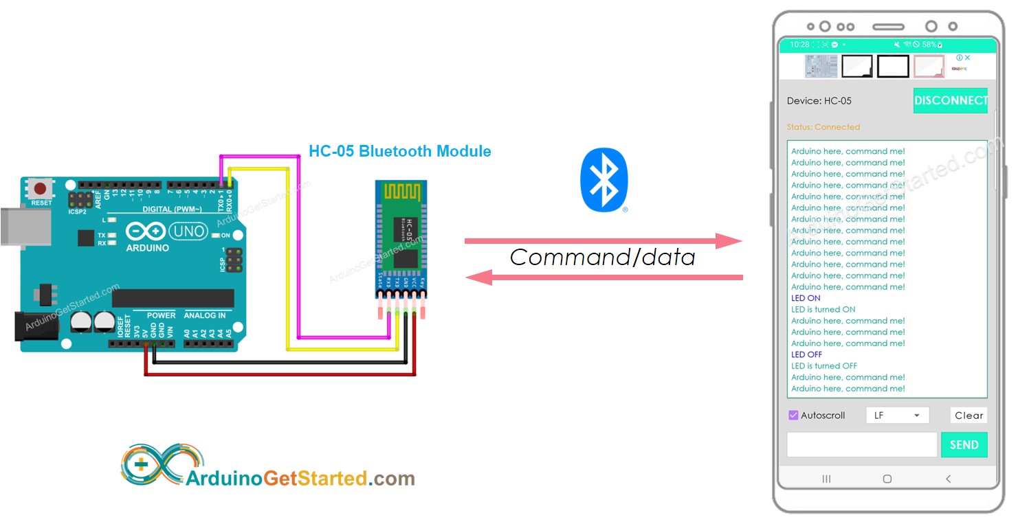
Arduino exchanges data with the smartphone app. The communication between two Arduino via Bluetooth will be presented in another tutorial.
You can use any Android/iOS app. This tutorial will use Bluetooth Serial Monitor App on Android for demonstration.
You can control anything connected to Arduino from the smartphone app. This tutorial will take LED and servo motor as examples.
This tutorial is about using Classic Bluetooth (Bluetooth 2.0). If you are looking for a Bluetooth Low Energy — BLE (Bluetooth 4.0), See this similar tutorial: Arduino — Bluetooth Low Energy
Hardware Required
Or you can buy the following sensor kit:
Please note: These are affiliate links. If you buy the components through these links, We may get a commission at no extra cost to you. We appreciate it.
About HC-05 Bluetooth Module
HC-05 is a Serial Bluetooth module. It works as a Serial to Bluetooth Converter. It does:
Receive data from the Serial RX pin and transmit the data to the paired device (such as a smartphone) via Bluetooth
More specifically, In the context of Arduino communicates with smartphone App (Android/iOS):
Pinout
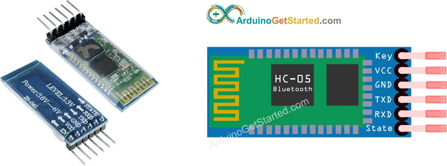
The HC-05 Bluetooth Module has 6 pins:
Enable/Key pin: This pin is used to toggle between Data Mode (set LOW ) and Command mode (set HIGH ). If not connected, it is in Data mode by default
TX pin: Serial data pin, connect this pin to the RX pin of Arduino. The data received via Bluetooth will be sent to this pin as serial data.
RX pin: Serial data pin, connect this pin to the TX pin of Arduino. The data received from this pin will be sent to Bluetooth
State: The state pin is connected to the onboard LED, it can be used as feedback to check if Bluetooth is working properly.
However, for basic functions, we just need to use 4 pins of The HC-05 Bluetooth Module to connect to Arduino.
The HC-05 Bluetooth Module also has two built-in components:
Button: can be used to control the Key/Enable pin to select the operation mode (Data or Command Mode)
How It Works
The HC-05 Bluetooth module has two operation modes:
Fortunately, The HC-05 Bluetooth module can work with Arduino by using the default setting without configuration.
HC-05 Default Settings
| Default Bluetooth Name | “HC-05” |
|---|---|
| Default Password | 1234 or 0000 |
| Default Communication | Slave |
| Default Mode | Data Mode |
| Default Data Mode Baud Rate | 9600, 8, N, 1 |
| Default Command Mode Baud Rate | 38400, 8, N, 1 |
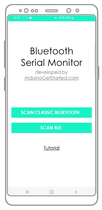
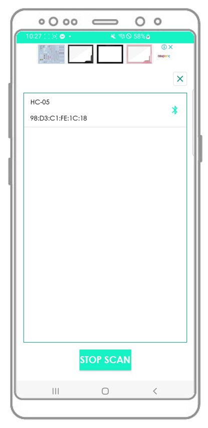
About Bluetooth Serial Monitor App
The Bluetooth Serial Monitor App is a mobile app that has the User Interface that looks like the Serial Monitor of Arduino IDE. It communicates with Arduino via Bluetooth. You can interact with Arduino via this app as if Serial Monitor on your PC, without adding any special code for the Bluetooth module in your Arduino code, by doing the following step:
And now you can send/receive data from Arduino just like the Serial Monitor of Arduino IDE. You do not need to modify the existing Arduino code or do not need to add any Bluetooth code to the new Arduino code.
Wiring Diagram
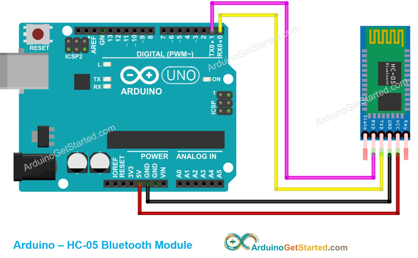
This image is created using Fritzing. Click to enlarge image
| Arduino Pins | HC-05 Bluetooth Pins |
|---|---|
| RX (Pin 0) | TX |
| TX (Pin 1) | RX |
| 5V | VCC |
| GND | GND |
| Enable/Key (NOT connected) | |
| State (NOT connected) |
You can use other Arduino pins by changing the Serial object in the Arduino code to another Serial1, Serial2. or SoftwareSerial if available.
How To Program For Bluetooth
No Bluetooth-dedicated code is required. We just need to use the Serial code.
Arduino sends data to Bluetooth App on Smartphone
To send data from Arduino to Bluetooth App on Smartphone, we need to use the following Arduino code:
In this example, we will send the “Arduino here, command me!” from Arduino to Bluetooth App on Smartphone every second
/* * Created by ArduinoGetStarted.com * * This example code is in the public domain * * Tutorial page: https://arduinogetstarted.com/tutorials/arduino-bluetooth */ void setup () < Serial . begin (9600); >void loop () < Serial . println ( "Arduino here, command me!" ); delay (1000); >
Quick Steps
Click Upload button on Arduino IDE to upload code to Arduino. You may be failed to upload the code to Arduino. If so, disconnect TX and RX pins from Bluetooth module, upload the code, and then reconnect RX/TX pin again.
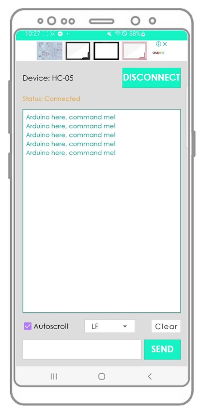
Arduino here, command me! Arduino here, command me! Arduino here, command me! Arduino here, command me! Arduino here, command me!
You will see that the data on the Serial Monitor of Arduino IDE and on the Android App are identical
Bluetooth App Send data To Arduino
Quick Steps
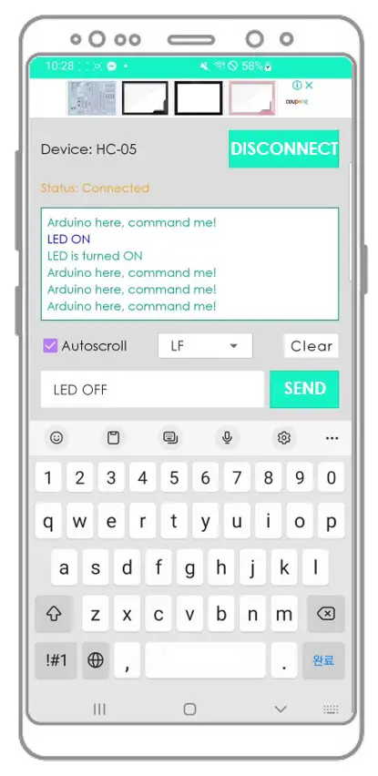
Arduino receives the data and prints the response to the Serial port. This data will be sent to the Bluetooth app
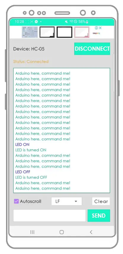
Arduino here, command me! Arduino here, command me! Arduino here, command me! Arduino here, command me! Arduino here, command me! Arduino here, command me! LED ON LED is turned ON Arduino here, command me! Arduino here, command me! Arduino here, command me! LED OFF LED is turned OFF Arduino here, command me! Arduino here, command me!
You will see that the data on the Serial Monitor of Arduino IDE and on the Android App are identical
Arduino Code — Control LED with smartphone App via Bluetooth
The below Arduino example code accepts two commands ( “ON” and “OFF” ) from Bluetooth Serial Monitor App to turn on/off a built-in LED.
You can see the instructions in more detail in Arduino controls LED via Bluetooth/BLE tutorial
Arduino Code — Control Servo Motor with smartphone App via Bluetooth
The below Arduino code received the angle value from Bluetooth Serial Monitor App to control the angle of the servo motor.
/* * Created by ArduinoGetStarted.com * * This example code is in the public domain * * Tutorial page: https://arduinogetstarted.com/tutorials/arduino-bluetooth */ // NOTE: change the Serial to other Serial/Software Serial if you connects Bluetooth module to other pins # include < Servo .h>Servo servo; // create servo object to control a servo int pos = 0; // variable to store the servo position void setup () < Serial . begin (9600); servo. attach (11); // attaches the servo on pin 11 to the servo object >void loop () < if ( Serial . available ()) < // if there is data comming int angle = Serial . parseInt (); if (angle >= 0 && angle <= 180) < servo. write (angle); // rotate servo Serial . print ( "Rotated servo to angle: " ); // reports action to smartphone app Serial . println (angle); >else < Serial . print ( "Invalid angle: " ); // reports invalid value to smartphone app Serial . println (angle); >> >
You can see the instructions in more detail in Arduino controls Servo Motor via Bluetooth/BLE tutorial
If the Bluetooth Serial Monitor app is useful for you, please give it a 5-star rating on Play Store. Thank you!
Video Tutorial
We are considering to make the video tutorials. If you think the video tutorials are essential, please subscribe to our YouTube channel to give us motivation for making the videos.
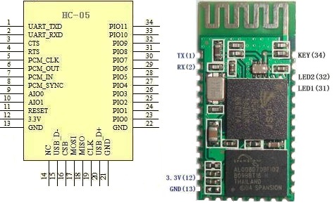
Pin Description
It has 6 pins,
1.Key/EN:It is used to bring Bluetooth module in AT commands mode. By default this pin operates in data mode. Key/EN pin should be high to operate Bluetooth in command mode. The default baud rate of HC-05 in command mode is 38400bps and 9600 in data mode.HC-05 module has two modes,

- Data mode: Exchange of data between devices. Baud rate is 9600bps in data mode.
- Command mode: It uses AT commands which are used to change setting of HC-05. Baud rate is 38400bps in command mode.
2. VCC: Connect 5 V or 3.3 V to this Pin.
3. GND: Ground Pin of module.
4. TXD: Connect with Microcontroller RXD pin of Microcontroller. Transmit Serial data (wirelessly received data by Bluetooth module transmitted out serially on TXD pin)
5. RXD: Connect with Microcontroller TXD pin of Microcontroller. Received data will be transmitted wirelessly by Bluetooth module.
6. State: It tells whether module is connected or not. It acts as a status indicator.
Package Information
HC-05

Hardware

For HC-05 Bluetooth Hardware Package details you can refer the document which we have provided at the end of article.
HC- 05 vs HC-06
| HC-05 | HC-06 |
|---|---|
| Master and slave mode can be switched | Master and slave mode can’t be switched |
| Bluetooth name: HC-05 | Bluetooth name: linvor |
| Password:1234 | Password:1234 |
| Master role: have no function to remember the last paired salve device. It can be made paired to any slave device. | Master role: have paired memory to remember last slave device and only make pair with that device unless KEY (PIN26) is triggered by high level. The default connected PIN26 is low level. |
| KEY: PIN34, for entering to the AT mode. | KEY: PIN26, for master abandons memory. |
| Default communication baud rate: 9600, 4800-1.3M are settable. | Default communication baud rate: 9600, 1200-1.3M are settable. |
| During the communication mode, by setting PIN34 to high the module can enter to the AT mode. | During the communication mode, the module can’t enter to the AT mode. |
| Pairing: Master device can’t only make pair with the specified Bluetooth address, it can also search and make pair with the slave device automatically. | Pairing: Master device search and make pair with the slave device automatically. |
Connecting HC-05 with Microcontroller

- Connect Power Supply(based on datasheet of modules) for Bluetooth and Microcontroller which you are using.
- Connect TXD pin of HC-05 Bluetooth module to RXD pin of Microcontroller.
- Connect RXD pin of HC-05 Bluetooth module to TXD pin of Microcontroller.
- Common grounding should be needed for both modules.
Applications
- Computer and peripheral devices
- GPS receiver
- Industrial control
- MCU projects
Modes of Operation
1. How to get to the AT Mode
- Step 1: Input low level to PIN34.
- Step 2: Supply power to the module.
- Step 3: Input high level to the PIN34. Then the module will enter to AT mode. The baud rate is as same as the communication time, such as 9600 etc.
- Step 1: Connect PIN34 to the power supply PIN.
- Step 2: Supply power to module (the PIN34 is also supplied with high level since the PIN34 is connected with power supply PIN). Then the module will enter to AT module. But at this time, the baud rate is 38400. In this way, user should change the baud rate at the AT mode, if they forget the communication baud rate.
How to get to the communication mode
- Step 1: Input low level to PIN34.
- Step 2: Supply power to the module. Then the module will enter to communication mode. It can be used for pairing.
2. How to set this module be the Master Role
- Step 1: Input high level to PIO11.
- Step 2: Supply power to the module. And the module will enter to the order-response work mode.
- Step 3: Set the parameters of the super terminal or the other serial tools (baud rate: 38400, data bit:8, stop bit:1, no parity bit, no Flow Control)
- Step 4: Sent the characters “AT+ROLE=1\r\n” through serial, then receive the characters “OK\r\n”. Here, “\r\n” is the CRLF.
- Step 5: Input low level to PIO, and supply power to the module again. Then this module will become master role and search the other module (slave role) automatically to build the connection.
- HC-03 and HC-05’s command should end up with “\r\n”. It’s different from HC-04 and HC-06 (They don’t need terminator).
- The most common commands for HC-03 and HC-05 are: AT+ROLE (set master –slave), AT+CMODE( set address pairing) , AT+PSWD (set password). If you want the master module has the function of remembering slave module, the most simply way is: First, set AT+CMODE=1. Make the master module pair with the slave module. Second, set AT+CMODE=0. Then the master module just can make pair with that specified slave module.
- When PIN34 keeps high level, all commands can be used. Otherwise, only some of them can be used.