- Bluetooth модуль JDY-08 4.0BLE с поддержкой AirSync iBeacon, чип CC2541
- JDY-08 : bluetooth 4.0 module
- Jean-Matthieu DECHRISTE
- Serial mode
- Breakout board
- Flash the device with HM10 firmware
- CC Debugger connection
- Flash the binary
- Test the new firmware
- Upgrade the HM10 firmware
- Annex: How I created the HEX file
- JDY-08 – Bluetooth 4.0 модуль на базе CC2541 с поддержкой iBeacon
- Bluetooth модуль JDY-08 (CC2541)
- Основные достоинства
- Примеры использования
Bluetooth модуль JDY-08 4.0BLE с поддержкой AirSync iBeacon, чип CC2541
BLE Bluetooth модуль, на микросхеме CC2541. Поддерживает несколько режимов работы, в том числе может работать в режиме IBeacon и c AirSync протоколом. По умолчанию работает в pass-through режиме(сквозном режиме). Может использоваться для удаленного U. Перейти к полному описанию
Доставка для г. Москва: Самовывоз сегодня до 20 часов: бесплатно Доставка до двери: 300 руб. Доставка в более чем 120 ПВЗ: загрузка
BLE Bluetooth модуль, на микросхеме CC2541. Поддерживает несколько режимов работы, в том числе может работать в режиме IBeacon и c AirSync протоколом. По умолчанию работает в pass-through режиме(сквозном режиме). Может использоваться для удаленного UART подключения к Arduino, — достаточно подключить его к RX-TX выводам, и к питанию вашего микроконтроллера. Подключиться к Arduino можно например с Android(программой Serial Bluetooth Terminal или любой с поддержкой BLE устройств) а так же iOS устройства. С компьютера можно подключиться, установив любую программу для работы с BLE модулями(без BLE программы, с компьютера BLE модули не видны в списке обнаруживаемых устройств).
Для конфигурации модуля, можно использовать АТ команды, — подключите модуль с помощью стандартного USB-TTL переходника:
| USB-TTL: | JDY-08: |
| GND | GND |
| +5V | VCC |
| RX | TX |
| TX | RX |
| GND | PWRC |
В любой терминальной программе, установите следующие настройки: скорость 115200 и Нет конца строки (No CR) . Теперь можно проверить работу AT команд, — введя AT+VER или AT+VID — все команды пишутся только заглавными и без пробелов.
JDY-08 : bluetooth 4.0 module
The JDY-08 BLE module is cheap and not very well documented. It’s mandatory to update it before unleashing it’s power!
Jean-Matthieu DECHRISTE

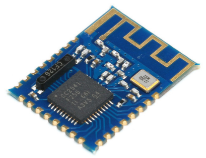
I recently bought a bluetooth LE module, the JDY-08.
It is a very small module, based on the TI CC2541 chip.
You can configure it with AT commands, on a serial line.
You can find the pinout on the kichMan github:
And some documentation on a shared Google doc.
And finally, the chinese datasheet.
The module has to be powered by 3.3V.
Warning: The firmware loaded by default on this module is not the same as on HM-10 or EY-08 modules, so the behavior is different.
I have the version JDY-08-V3.383
Serial mode
Now, you can send AT commands. Please notice:
- The commands are key sensitive
- The default baudrate is 115200
- Don’t send newline characters, the module will not uderstand the AT command.
- You have to write the whole command in one time, and not characters by characters (i.e. will not work in Putty).
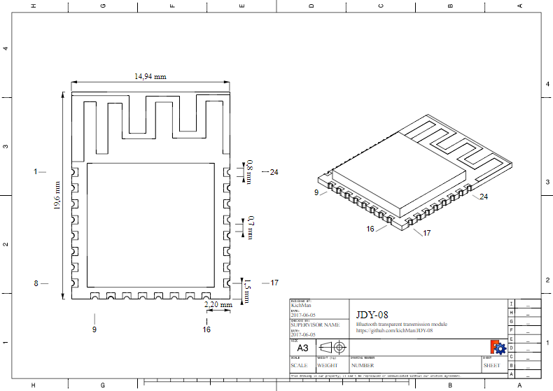
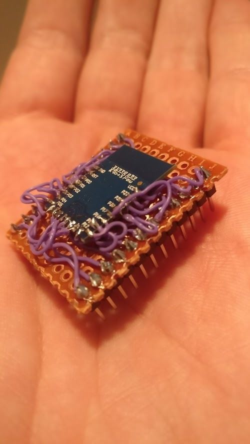
Breakout board
As the device doesn’t have a 2.54mm pitch, I build a custom breakout board for developpement purposes.
I hope I will be able to find a real / create a real PCB one day.
Flash the device with HM10 firmware
The firmware I have on one of my chip seems defective.
To be able to use it, I want to flash it with the HM10 firmware, based on the same chip (CC2541).
CC Debugger connection
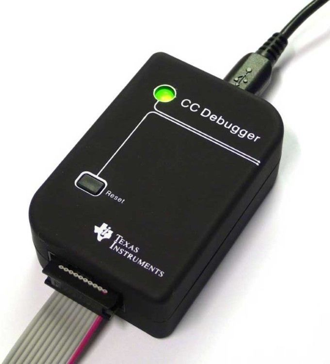
I bought a CC Debuger :
You can also do it with an arduino, but it’s less simple.
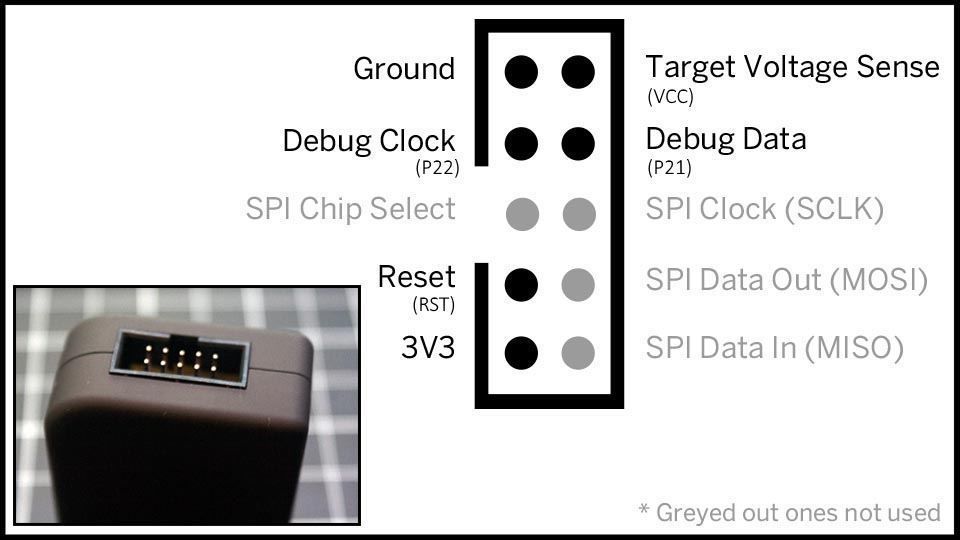
To connect it to the device, follow those instructions :
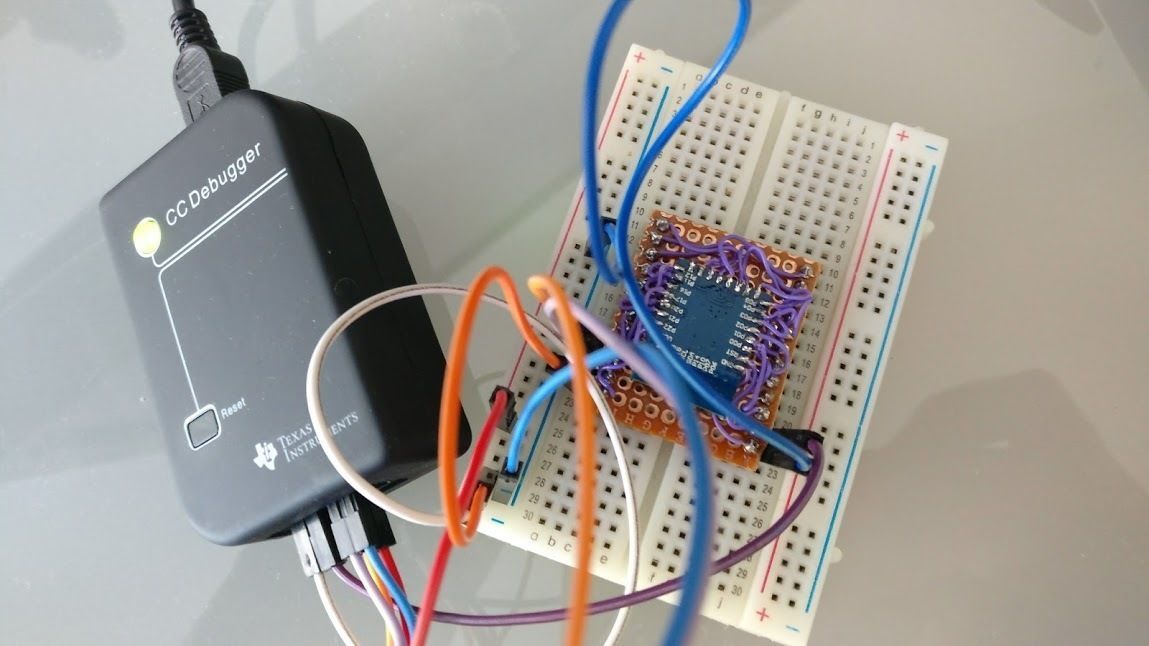
In picture :
After powering the probe, the LED goes from red to green.
Flash the binary
To flash the new firmware, you need to download the SmartRF Flash Programmer from TI, and the firmware V550 (CC2541hm10v550.hex) that I created (see at the end of the post) — or the V540 (CC2541hm10v540.hex).
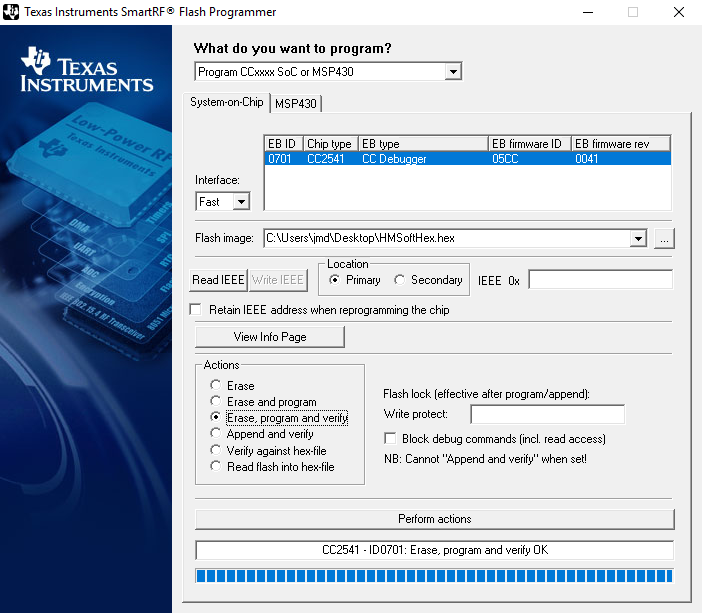
- Launch «SmartRF Flash Programmer»
- Select your proble if it’s not selected by default
- Select the hex file (firmware)
- Uncheck «Retain IEEE address. «
- Select «Erase, progra and verify»
- Click on «Perfom actions» and wait the end of the process
After that, you should already be able to see the device with your phone, named «HMSoft».
Test the new firmware
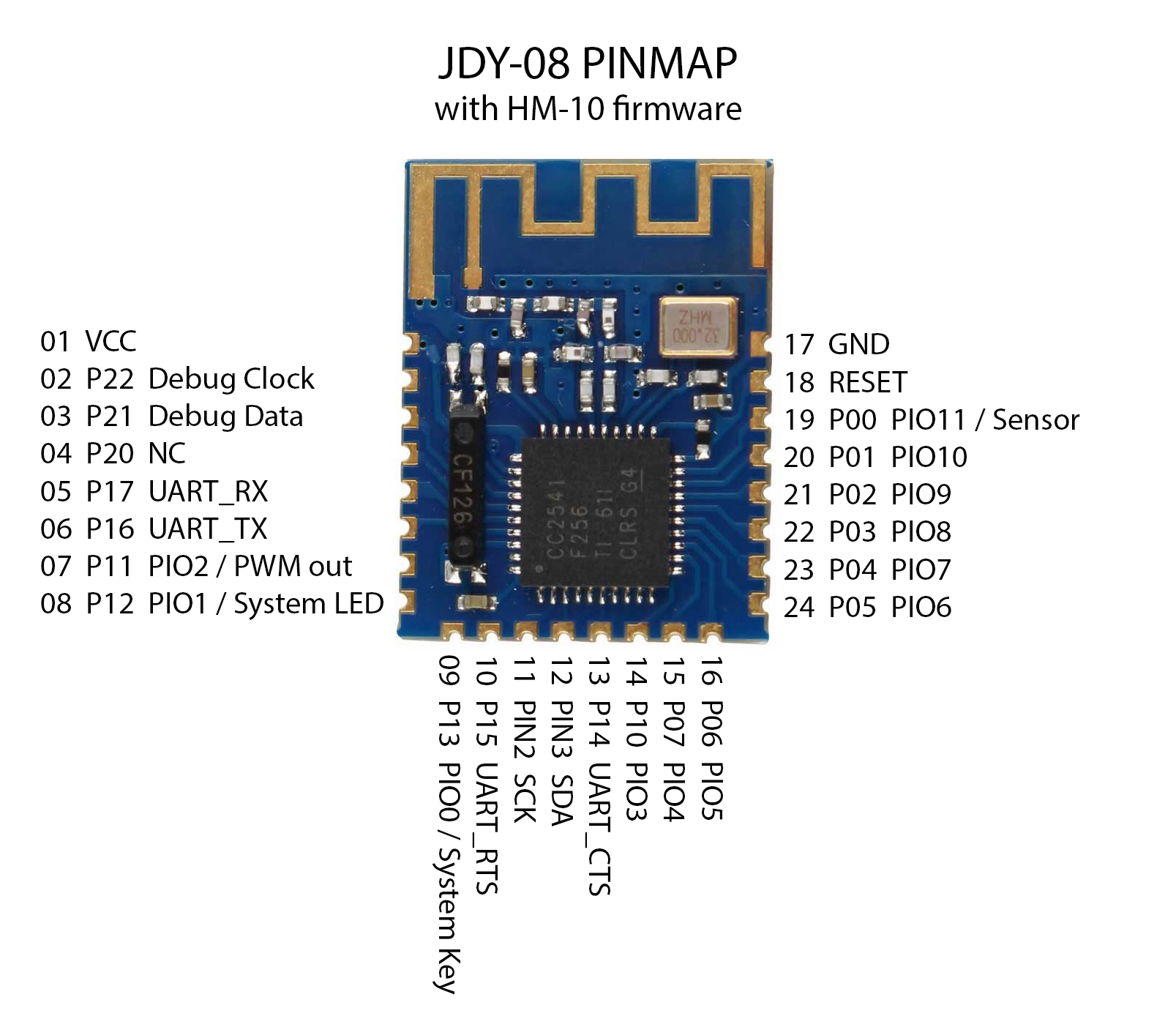
After flashing the HM-10 firmware, the pinout changed [1] :
- P13 to GND is used to exit sleep mode or disconnect the module if connected (and not P00 anymore)
- P17 become UART RX
- P16 become UART TX
To send AT commands to the module through UART interface, the pin 09 (marked P13 on JDY-08, or the PIO0 on the HM-10) must be pulled down (GND) for at least 1 second after the board power on and after every bluetooth connection established.
Moreover, the factory default setting with HM10 firmware:
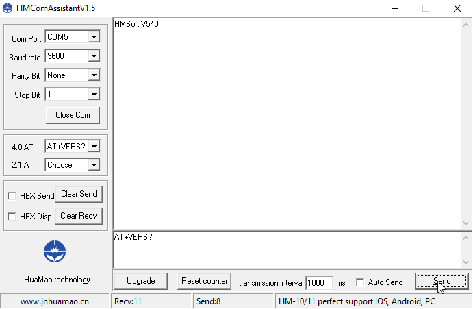
To test the command line, you can send AT (expected response OK ) ou AT+VERS? .
To reset factory settings, send AT+RENEW (expected response OK+RENEW ).
The software HMComAssistant.exe can help you to connect and exchange data with this firmware.
Upgrade the HM10 firmware
Once that a HM10 firmare has been flashed on the JDY08 module, you can upgrade the firmware with a serial connection.
- Send AT+SBLUP to the module (expected response: OK+SBLUP )
- Close the COM port or your software used to send commands to the device
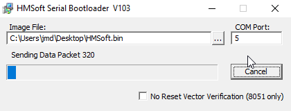
- Launch the HMSoft.exe software
- Select the new HM10 firmware file (bin), the COM port and click on «Load Image». The transfer should begin, and at the end, you should see «Download completed successfully».
Annex: How I created the HEX file
First, I tried to download the last firmware version (HM-10 HMSoft CC2541 V550 firmware upgrade file. 2017), extract the HMSoft.bin file, and transform it into a hex file with srecord :
srec_cat.exe HMSoft.bin -Binary -o HMSoftHex.hex -Intel
If found another file that seemed to work for some guys, named CC2541hm10v540.bin.
With this file, I created a hex file ( srec_cat.exe CC2541hm10v540.bin -Binary -o CC2541hm10v540.hex -Intel ), and I flashed it as explained before.
After that, I upgraded the firmware through serial port, with the last binary found on the manufacturer website (V550 the 2017-08-21).
As I did not activate the read lock, I was able to read the new firmware and create the final HEX file for the V550.
JDY-08 – Bluetooth 4.0 модуль на базе CC2541 с поддержкой iBeacon

Беспроводной модуль Bluetooth-трансивера JDY-08 BLE 4.0 построен на специализированной микросхеме CC2541 производства Texas Instruments, представляющей собой оптимизированное по мощности решение на основе системы на кристалле (SoC) c Bluetooth и низким энергопотреблением. Позволяет создавать надежные сетевые узлы с низкими затратами.
Модуль удобнее использовать со специальной базовой макетной платой, имеющей выводные контакты под разъем 2.54 мм.
Москва и МО: Самовывоз
Курьерская доставка
Россия и СНГ: СДЭК
Почта РФ / Достависта
Купить JDY-08 — Bluetooth 4.0 модуль на базе CC2541 с поддержкой iBeacon в Москве или с доставкой по России и СНГ очень просто — до покупки осталось всего 3 клика!
- Добавьте товар в корзину
- Оформите заказ, выбрав наиболее удобный способ доставки и оплаты
- Дождитесь подтверждения от менеджеров или позвоните самостоятельно
- Оплатите заказ удобным способом и получите его в ближайшее время
Bluetooth модуль JDY-08 (CC2541)
Модуль работает на рабочей частоте 2,4 ГГц и поддерживает скорости передачи данных:
Протокол шифрования/дешифрования – AES-128L2CAP , программируемая выходная мощность модуля – до 0 дБм. Модуль управляется AT-командами через UART интерфейс.
Чувствительность приемника: -94 дБм при скорости передачи 1 Мбит/с.
Стандарт модуля — Bluetooth 4.0 с поддержкой режима пониженного энергопотребления и работы с IBeacon. Максимальный потребляемый ток — 20 мА, ток режима энергосбережения — 0,5 мкА (ожидание внешнего прерывания).
Основные достоинства
- Поддерживает все современные протоколы связи Bluetooth
- Малые габариты и низкое энергопотребление, позволяющие использовать модуль в миниатюрных устройствах
- Высокая помехозащищенность
Примеры использования
- Разработка Систем обмена данными проектов ARDUINO «Умный дом»
- Интеграция в платформу «Интернет вещей»
- Системы дистанционного видеонаблюдения