- Xunlong Orange Pi 2
- Contents
- Identification
- Sunxi support
- Current status
- Manual build
- U-Boot
- Mainline U-Boot
- Linux Kernel
- Sunxi/Legacy Kernel
- Mainline kernel
- Tips, Tricks, Caveats
- FEL mode
- LEDs
- Expansion Ports
- Adding a serial port
- Locating the UART
- Pictures
- Variants
- Also known as
- See also
- Xunlong Orange Pi
- Contents
- Identification
- Sunxi support
- Current status
- Images
- HW-Pack
- BSP
- Manual build
- U-Boot
- Sunxi/Legacy U-Boot
- Mainline U-Boot
- Linux Kernel
- Sunxi/Legacy Kernel
- Mainline kernel
- Expansion Port
- Tips, Tricks, Caveats
- FEL mode
- LEDs
- SATA
- Adding a serial port
- Locating the UART
Xunlong Orange Pi 2
Orange Pi 2 is H3 based development board produced by Xunlong. The concept is based on the original Orange Pi. Both, Orange Pi 2 and its smaller cousin Orange Pi Mini 2 (similar to Orange Pi Mini) were released in March 2015. The board is based on a quad-core H3 CPU, and offers a TF card slot, onboard Ethernet (10/100M Ethernet RJ45) and WiFi (802.11 b/g/n), 40 pin GPIO and 4 x USB type A connectors, but does not come with the SATA port like the A20 based original Orange Pi did.
Contents
- 1 Identification
- 2 Sunxi support
- 2.1 Current status
- 2.2 Manual build
- 2.2.1 U-Boot
- 2.2.1.1 Mainline U-Boot
- 2.2.2.1 Sunxi/Legacy Kernel
- 2.2.2.2 Mainline kernel
- 3.1 FEL mode
- 3.2 LEDs
- 3.3 Expansion Ports
- 4.1 Locating the UART
Identification
The PCB has the following silkscreened on it:
Sunxi support
Current status
The H3 SoC support has matured since its introduction in kernel 4.2. Most of the board functionality for boards such as Orange Pi 2 are available with current mainline kernels. Some features (hw accelerated crypto, hw spinlocks, and thermal) are still being worked on. For a more comprehensive list of supported features, see the status matrix for mainline kernels. In addition, legacy 3.4 kernels are available in various work-in-progress git branches.
See the Manual build section for more details.
Manual build
You can build things for yourself by following our Manual build howto and by choosing from the configurations available below.
U-Boot
Mainline U-Boot
Use the orangepi_2 (supported since v2016.05) build target. The U-Boot repository and toolchain is described in the Mainline U-Boot howto.
The H3 boards can boot from SD cards, eMMC, NAND or SPI NOR flash (if available), and via FEL using the OTG USB port. In U-Boot, loading the kernel is also supported from USB or ethernet (netboot). HDMI support in U-Boot is still WIP.
Linux Kernel
Sunxi/Legacy Kernel
The 3.4 kernel from the official Allwinner’s git repository does not support H3 yet. But it is possible to use one of the kernel forks, based on the lichee H3 SDK tarball:
Configure this kernel using sun8i_h3_defconfig, the rest is explained in the kernel compilation guide.
Use the .fex file for generating script.bin. The .fex file can be found here for now orangepi2.fex. This was extracted from the android sdcard image.
When booting the legacy 3.4 kernel with the mainline U-Boot, add the following line to boot.cmd:
setenv machid 1029 setenv bootm_boot_mode sec
Some other legacy kernel repositories:
- 3.4-lichee-based kernel, based on work by ssvb and loboris
- Yocto support here glues together all the required parts to get this kernel to work with mainline u-boot, as well as accelerated X11/GLES support
- A newer H3 BSP variant appeared with tons of fixes which has been made available by FriendlyARM.
- A cleaned up fork has been adopted by Armbian project. On top of that Armbian maintains a bunch of 3.4.x patches for H3 devices.
Mainline kernel
The mainline kernel has good support for the H3 SoC. Please refer to the status matrix for a more detailed list of the development process, links to patches and links to kernel fork repositories. Minor drivers that are currently work-in-progress may require a) third party patches (see also arm-linux mailing list) or b) a pre-patched distro (e.g. Armbian).
Repositories with H3 patches:
- Ondřej Jirman’s branch for H3 based orange Pi (kernel 4.19) (work-in-progress DVFS)
- Thermal regulation (if CPU heats above certain temperature, it will try to cool itself down by reducing CPU frequency)
- HDMI audio support (from Jernej Skrabec)
- Configure on-board micro-switches to perform system power off function
- Wireguard (https://www.wireguard.com/)
Use the sun8i-h3-orangepi-2.dtb device-tree binary.
Tips, Tricks, Caveats
FEL mode
The button marked SW3, located between the HDMI and TTL UART, triggers FEL mode when pressed during boot.
To verify you have successfully entered FEL mode, check the output of fel version . For the Orange Pi 2, it should look like:
AWUSBFEX soc=00001680(unknown) 00000001 ver=0001 44 08 scratchpad=00007e00 00000000 00000000
LEDs
For those with a transparent case (or no case at all) the Orange Pi 2’s LED activity is good. The red power LED (D7) can be turned off.
Expansion Ports
The Orange Pi 2 exposes a 2.54mm pitch connector.
Extension Header 1×40 Header 1 3.3V 2 VCC-5V 3 PA12 (TWI0-SDA/DI_RX/EINT12) 4 VCC-5V 5 PA11 (TWI0-SCK/DI_TX/EINT11) 6 GND 7 PA6 (SIM_PWREN/PWM1/PA_EINT6) 8 PA13 (SPI1_CS/UART3_TX/PA_EINT13) 9 GND 10 PA14 (SPI1_CLK/UART3_RX/PA_EINT14) 11 PA1 (UART2_RX/JTAG_CK0/PA_EINT1) 12 PD14(RGMII_NULL/MII_TXERR/RMII_NULL) 13 PA0 (UART2_TX/JTAG_MS0/PA_EINT0) 14 GND 15 PA3 (UART2_CTS/JTAG_DI0/PA_EINT3) 16 PC4 (NAND_CE0) 17 3.3V 18 PC7 (NAND_RB1) 19 PC0 (NAND_WE/SPI0_MOSI) 20 GND 21 PC1 (NAND_ALE/SPI0_MISO) 22 PA2 (UART2_RTS/JTAG_DO0/PA_EINT2) 23 PC2 (NAND_CLE/SPI0_CLK) 24 PC3 (NAND_CE1/SPI0_CS) 25 GND 26 PA21 (PCM0_DIN/SIM_VPPPP/PA_EINT21) 27 PA19 (PCM0_CLK/TWI1_SDA/PA_EINT19) 28 PA18 (PCM0_SYNC/TWI1_SCK/PA_EINT18) 29 PA7 (SIM_CLK/PA_EINT7) 30 GND 31 PA8 (SIM_DATA/PA_EINT8) 32 PG8 (UART1_RTS/PG_EINT8) 33 PA9 (SIM_RST/PA_EINT9) 34 GND 35 PA10 (SIM_DET/PA_EINT10) 36 PG9 (UART1_CTS/PG_EINT9) 37 PA20 (PCM0_DOUT/SIM_VPPEN/PA_EINT20) 38 PG6 (UART1_TX/PG_EINT6) 39 GND 40 PG7 (UART1_RX/PG_EINT7) Adding a serial port

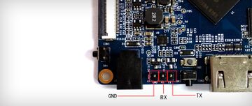
Locating the UART
The UART pins are located on J3 between DC input and Uboot Button(SW3) of the board. They are marked as TX, RX and GND on the PCB. Just attach some leads according to our UART Howto.
Pictures
Variants
- The original Orange Pi was released in November 2014. The Orange Pi features a standard TF card slot and a 26 pin GPIO connector (similar to the Raspberry Pi A/B).
- The smaller cousin Orange Pi Mini 2 (similar to Orange Pi Mini) were also released in March 2015.
Also known as
See also
There are several websites about Orange Pi 2 and claiming to support it. It has to be clarified, what is «official» and who is behind this sites.
Currently only an android image for an sdcard is provided via OrangePi’s Website.
Xunlong Orange Pi
Orange Pi is A20 based development board produced by Xunlong. The Orange Pi was released in November 2014 and featured a standard TF card slot and a 26 pin GPIO connector (similar to the Raspberry Pi A/B). The Orange Pi franchise has later been supplemented with other Orange Pi boards, but only the original Orange Pi and Orange Pi Mini are actually based on A20.
Contents
- 1 Identification
- 2 Sunxi support
- 2.1 Current status
- 2.2 Images
- 2.3 HW-Pack
- 2.4 BSP
- 2.5 Manual build
- 2.5.1 U-Boot
- 2.5.1.1 Sunxi/Legacy U-Boot
- 2.5.1.2 Mainline U-Boot
- 2.5.2.1 Sunxi/Legacy Kernel
- 2.5.2.2 Mainline kernel
- 4.1 FEL mode
- 4.2 LEDs
- 4.3 SATA
- 5.1 Locating the UART
- 7.1 A20 based
- 7.2 Other SoCs
- 9.1 Manufacturer images
Identification
The PCB has the following silkscreened on it:
Sunxi support
Current status
Supported, but no longer manufactured by Xunlong. (2016-05-24)
Note: Orange Pi’s GMAC is not supported in the community kernel. A commit within Orange Pi Github fork of linux-sunxi-3.4 seems to provide GMAC support for Orange Pi. This has to be proved and merged into linux-sunxi.
Xunlong seems to use an important tweak of both the Linux 3.4 kernel and U-Boot networking code for the Orange Pi: The GMAC driver is specifically modified to set the GMAC_TX_DELAY parameter to 3. This adjusts the relative timing of the clock and data signals to the PHY in order to compensate for differing trace lengths on the PCB (details; the pcDuino3 Nano has the same problem). Without this modification, the Ethernet port will work at 100Mbit, but not (or not reliably) at 1000Mbit. Upstream U-Boot now sets this parameter itself, so the kernel patch isn’t needed any more (patch).
Images
HW-Pack
BSP
Manual build
You can build things for yourself by following our Manual build howto and by choosing from the configurations available below.
U-Boot
Sunxi/Legacy U-Boot
The .fex file can be found in sunxi-boards as orangepi.fex
Mainline U-Boot
For building u-boot, use the orangepi target ( make orangepi_config ).
Linux Kernel
Sunxi/Legacy Kernel
Mainline kernel
Use the sun7i-a20-orangepi.dtb device-tree file for the mainline kernel
Expansion Port
The Orange Pi has a 26-pin, 0.1″ connector with several low-speed interfaces.
2×13 Header 1 3.3V 2 5V 3 PB21 TWI2-SDA 4 5V 5 PB20 TWI2-SCK 6 GND 7 PI3 PWM1 8 PH0 UART3_TX 9 GND 10 PH1 UART3_RX 11 PI19 UART2_RX 12 PH2 13 PI18 UART2_TX 14 GND 15 PI17 UART2_CTS 16 PH20 CAN_TX 17 3.3V 18 PH21 CAN_RX 19 PI12 SPI0_MOSI 20 GND 21 PI13 SPI0_MISO 22 PI16 UART2_RTS 23 PI11 SPI0_CLK 24 PI10 SPI0_CS0 25 GND 26 PI14 SPI0_CS1 The Orange Pi also has a 18-pin, 0.1″ connector with several low-speed interfaces.
2×9 Header 1 5V 2 3.3V 3 PH5 4 PI21 UART7_RX 5 PH3 6 PI20 UART7_TX 7 GND 8 GND 9 RESET# 10 LRADC1 11 ADC_Y2 12 LRADC0 13 ADC_Y1 14 GND 15 ADC_X2 16 UART0_RX 17 ADC_X1 18 UART0_TX Tips, Tricks, Caveats
FEL mode
The button marked SW2, located between the VGA and USB host connectors, triggers FEL mode when pressed during boot. (SW2 pulls the A20 BOOTSEL pin to low level.)
If no SD card is present, the A20 will automatically fall back to FEL mode (as this device has no other means of booting, like e.g. onboard NAND flash). So if you want to enforce FEL mode, you may simply remove the SD card and connect to the Orange Pi via the DC input(the one next to the audio output). This also supplies power to the board at the same time.
To verify you have successfully entered FEL mode, check the output of fel version . For the Orange Pi, it should look like:
AWUSBFEX soc=00001651(A20) 00000001 ver=0001 44 08 scratchpad=00007e00 00000000 00000000
LEDs
For those with a transparent case (or no case at all) the Orange Pi’s LED activity is good. The red power LED (D2) can be turned off.
SATA
If you wish to connect a SATA drive (2.5″ mobile harddisk or SSD) to the Orange Pi: Make sure your power supply is connected to the «DC-IN» port, and can deliver sufficient current (e.g. 5V/2000mA). Using the OTG port or an inadequate power supply might result in your SATA device not being detected.
Adding a serial port
TODO: The section is mostly a copy&paste from the «Banana Pi» page. Some of it may be incorrect, or might not apply to this device. Please review / rework the information, and remove this reminder when done.
While the GPIO pinout of the Orange Pi is designed to be compatible to the Raspberry Pi, it’s important to notice subtle differences in the serial ports. The Orange Pi has some additional pins that already provide two more serial ports.
The default serial port /dev/ttyS0, used for (bootstrap) debugging and the serial console, is located at J11 — refer to the picture and instructions below. The Raspberry’s «original» serial port on GPIO 14 and 15 (CON3, pins 8 and 10) can usually be accessed as /dev/ttyS2 on the Orange Pi. J12 also provides another serial port on pins 4 (RXD) and 6 (TXD), which should map to /dev/ttyS3.
Note: The actual mapping between physical pins, UART numbers and/or device names may depend on the specific kernel and configuration used. If in doubt, check the boot messages: dmesg | grep -i uart
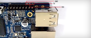
Locating the UART
The UART pins are located in the upper right corner of the board. They are marked as TX, RX and GND on the PCB. Just attach some leads according to our UART Howto. Do not connect the red wire (VCC or 3.3V/5V), as that might damage your board.
- 2.5.1 U-Boot
- 2.2.1 U-Boot