- Building a Computer for Linux
- To see the full content, share this page by clicking one of the buttons below
- About danroo
- Related Articles
- Preparation For The Boat Battle – Ark Survival Evolved
- how to make animated videos | cartoon video kaise banate hain
- Shawn Blanton: Building Defect-Free Computer Chips
- Check Also
- This Necromancer Build Has Insane DPS | Diablo 4 Necromancer
- 10 comments
- Making embedded Linux computer
Building a Computer for Linux
Today we will talk about planning to build a computer to run Linux. By and large, computers are fairly easy to build today and the cost is way cheaper than buying one that is pre-built.
#Linux #Computers #CustomBuild
To see the full content, share this page by clicking one of the buttons below
———–
Support Switched to Linux!
? Merch:…
source
Concluzion: Building a Computer for Linux – Switched to Linux,Technology,Privacy,Linux
About danroo
Related Articles
Preparation For The Boat Battle – Ark Survival Evolved
how to make animated videos | cartoon video kaise banate hain
Shawn Blanton: Building Defect-Free Computer Chips
Check Also
This Necromancer Build Has Insane DPS | Diablo 4 Necromancer
This Necromancer Build Has Insane DPS | Diablo 4 Necromancer Endgame Build #Necromancer #Build #Insane …
10 comments
Always check the QVL lists first. That is key. AsRock is seemingly the best for memory compatibility. It has to be compatible with you’re chipset.
The amd 6500 gpu is garbage, do not pair with a system with a pcie 3 slot or pcie 3 cpu, you will be stuck with x4 bandwidth instead of x16. Its not a big deal on a pcie 4 system but that requires a zen 3 cpu or 11 gen intel or newer.
Just my 2 cents, but I would have stayed with the 5600X for $209 over the older 3600X for $370 (way, way overpriced). My understanding is that Zen 3 runs fine with Linux Kernel 5.10 or higher. For reference, Ubuntu 22.04 is on kernel 5.15, LMDE 5 is on 5.10, and KDE Neon is on 5.13. Even if you want to run Linux Mint 20.3, which defaults to 5.04, the Update Manager has a Kernel Manager that makes it very simple to upgrade to kernel 5.13. I have been running Mint on 5.13 for a while, and it has been very stable.
For sound cards, I have a Creative Audigy 2 gold edition at home I still love. Old as dirt, but still one of my favorites.
I have the same exact laptop that Dan showed, had Vista on it years ago, now it has LMDE4, runs incredibly well for an old 32 bit machine.
It is not quite true that SSD’s always all of the sudden die, that was the case but improved a lot!. There is proper wear-leveling built in, just have enough of the capacity free to facilitate proper wear-leveling if required. The controller keeps track of the number of writes and it blocks writing after a certain number got reached, you can still read and save all the data. It depends on the model of SSD though so don’t cheap out.
In regard to motherboards: I have a Gigabyte and it is fine but I do have a rather slow POST (9 seconds). I don’t trust ASUS and ASRock is quite bad at the low-end (see Hardware Unboxed). ASUS sold a graphics card (5700 (XT)) which literally had no cooling of the memory and poor cooling of the GPU, this was caused by ASUS using screws which are too long because at that moment they lackec manual labor and machines can not handle the shorter screws due to torque-tolerance.
Indeed, Ryzen-CPU’s need faster RAM, but Intel profits from it too, just less. Go with 3600 MT/s and CL=16 DDR4 because it is not that much more expensive than 3200 MT/s. For the CPU it does not matter whether you pick AMD or Intel but for some reason lm-sensors can not access my CPU-fan-rpm , the motherboard takes care of it and indirectly based on temperature you can look up in your UEFI-menu which rpm it is. Not ideal.
If you choose a Nvme-SSD, choose a fast one. Otherwise you will eventually end up with spare Nvme-SSD’s and you will one day have to buy some adapter to still use those, because there is place for only 2 Nvme-SSD’s in a motherboard at the moment. I already am at that stage: I started with 660p from Intel, it sucks. Now a 970 Evo. When I upgrade to PCIe4/PCIe5 in the future I need such card for the spare Nmve-SSD’s or not use it anymore. Pick 2 MB of RAM per core. Do NOT cut corners on the PSU. Pick a case with good ventilation, preferably have 140 mm fans (silent bearing) or larger for the case. Less noise. General recommendation: go for the sweet-spot in the midend to high midend, wherever you get the most bang for the bucks. Don’t buy the most powerful CPU and GPU but don’t cheap out either. Never cheap out on the PSU.
LOL – what part of the Pre-2010 Era do «Swap-Files» indicate? – LOL
. lets get-out our Gateways and go for it – LOL
Windows Vista/Cinnamon is still with us today as well as Windows XP/KDE . . . so . . . where’s the New Stuff?
You made a mistake by putting in the RX 6500 XT… That card doesn’t have a decent graphics driver in it…no screen capture ability and no sound drivers…things you look for in a functional graphics card… If you want to do anything involving a YT broadcast…those three things are a must…
Making embedded Linux computer
All of the best integrated circuits today come in hard to solder BGA packages. Because BGA packages have connections under the chip soldering is harder and it needs to be done using a reflow oven or hot plate. Another problem is with designing the PCB, vias and traces need to be small enough to fit between the solder balls and there needs to be usually quite many layers in the board to make room for all the closely packed traces. This means that a cheap Chinese two layer board doesn’t have enough room and more layers are needed. Adding layers increases the cost of the board dramatically when ordering only a few copies.
I wanted to try designing a board with BGA chips in it to see how hard soldering them could be. So I decided to design a small ARM embedded system that can run Linux. ARM processor that I decided to use was AT91SAM9N12 in a 217 ball LFBGA package, just because it was the cheapest ARM processor with memory management unit which is required to run Linux. Originally I wanted to have only one BGA chip, but RAM in BGA package was significantly cheaper than in other packages and I decided to also have DDR2 memory in a BGA package.
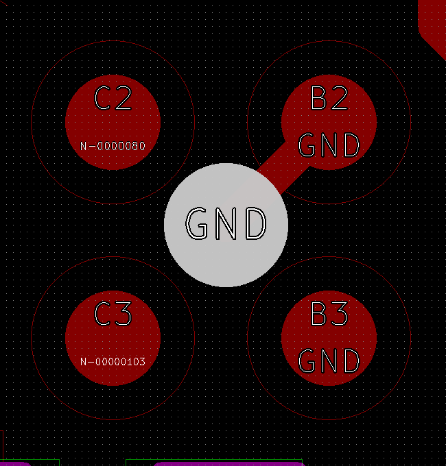
Positioning VIA for maximum amount of space.
Finding a manufacturer for the board turned out to be a slightly challenging task. Two layers wouldn’t be enough and at least four layers would be needed. Ball diameter of the 217-LFBGA package is 0.4 mm and distance between adjacent balls is 0.8 mm. To make a little bit more room for the vias ball land pattern can be made slightly smaller than the solder ball. I used 0.36 mm pads. Putting via between the four balls maximises the available space. Manufacturer needs to be able to make a via that fits in about 0.8 mm space. Almost any manufacturer can make a via with this diameter, but the problem is that this distance includes via drill diameter, two times the annular ring around the via and two times the minimum distance between via and trace. For example iTead’s four layer board has minimum via drill diameter of 0.3 mm, minimum annular ring width of 0.15 mm and minimum 0.15 mm between via and trace. This adds up to 0.9 mm which means that minimum sized via can’t fit between the BGA balls. The only reasonably priced manufacturer I found was OSH parks. Their four layer board has smaller limits and via can just barely fit between the BGA balls. As a bonus it’s also cheaper than iTead for small board.
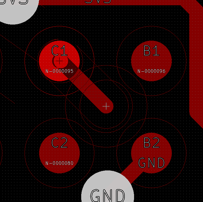
Minimum via with OSH park design rules, fits just barely
Even though the via can fit between the BGA balls, there are still some problems: There is not enough room for trace to go between two vias. This means that it’s not possible to route the BGA using standard escape routing where every pad has one via. This means that board needs to have enough unconnected pads on the perimeter, so that traces from the inside can be routed. Fortunately the processor has many general I/O- pins that are left unconnected.
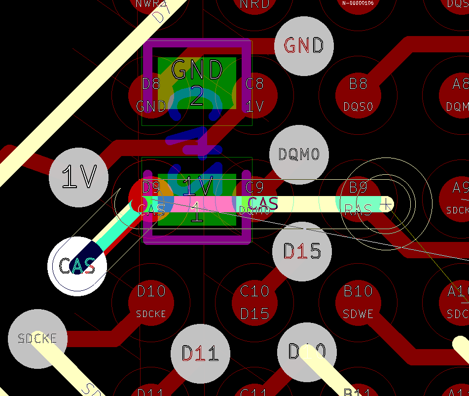
. but trace doesn’t fit between two vias without violating the design rules. CAS trace doesn’t have enough room to fit between DQM0 and D15 vias.
Manufacturing concerns solved, it’s time to start thinking what components should be on the board. I don’t really care about the usefulness of the board and this whole project is more of a learning experience. To keep the costs down board size needs to be kept small. This means that there won’t be space for any extra interfaces like ethernet, serial ports or SD-card.
Besides the processor and RAM other essential components are: mass memory, voltage regulators and supervisor circuit for handling the reset of the chip. Processor can boot from the NAND, but I decided to also have Dataflash for the bootloader just in case, though this ended up being left unpopulated. For mass memory NAND flash is a good choice because it’s cheap with big capacity. Having it also in a BGA package would have been cheaper, but I already have enough trouble with two BGA packages, so I decided to use 4Gb NAND in a 48 pin TSOP package.
Connecting the components is explained well in the processor’s datasheet, but because the document is over 1000 pages long it might be hard to find all the details. Atmel also publishes schematics of the evaluation boards that are very helpful when designing a board.
Some freedom needs to be taken with DDR2 traces. Normally traces should be length matched, have controlled impedance and terminating or series resistors. Reference design from the development board uses series resistors in all of the DDR2’s signals. I don’t have enough room for them so I just decided to leave them out. Impedance isn’t 50 ohms either, because I had to use smaller traces to fit everything. I hoped that because RAM is so close to the processor, lack of series resistors and impedance mismatch wouldn’t matter. All traces from CPU to RAM are about 25 mm long. Usual rule of thumb is that if trace length is over 10 % of wavelength of the signal then transmission line effects should be taken into account. In this case it would mean that frequency should be roughly above 1 GHz. RAM clock frequency is only 133 MHz and even the first few harmonics are under the 1 GHz, which suggests that this should work fine. Just to be sure I matched the trace lengths within few millimeters, but this might have been unnecessary.
Voltage supplies are bit complicated. Processors core voltage is 1.0 V, RAM needs 1.8 V and NAND needs 3.3 V. Because the input voltage is 5 V from USB, board needs to have three different voltage regulators. Normally it would be good to reserve one layer on the board for power supplies and keep it free from signal traces to lower power supply impedance, but board only has four layers and one of them is used for ground plane. This would mean that there would be only two layers left for signals which wasn’t enough. So I didn’t have separate power supply layer and instead made several planes in different layers for different power supplies.
Losses with linear regulators would have been too big for USB powered applications in the worst case, so I decided to have 3.3 V regulator as a more efficient switching regulator. 1.0 V and 1.8 V regulators are linear regulators that have 3.3 V as input voltage. Because linear regulators losses depend on the difference between input and output voltage using 3.3 V as input instead of 5 V increases the efficiency.
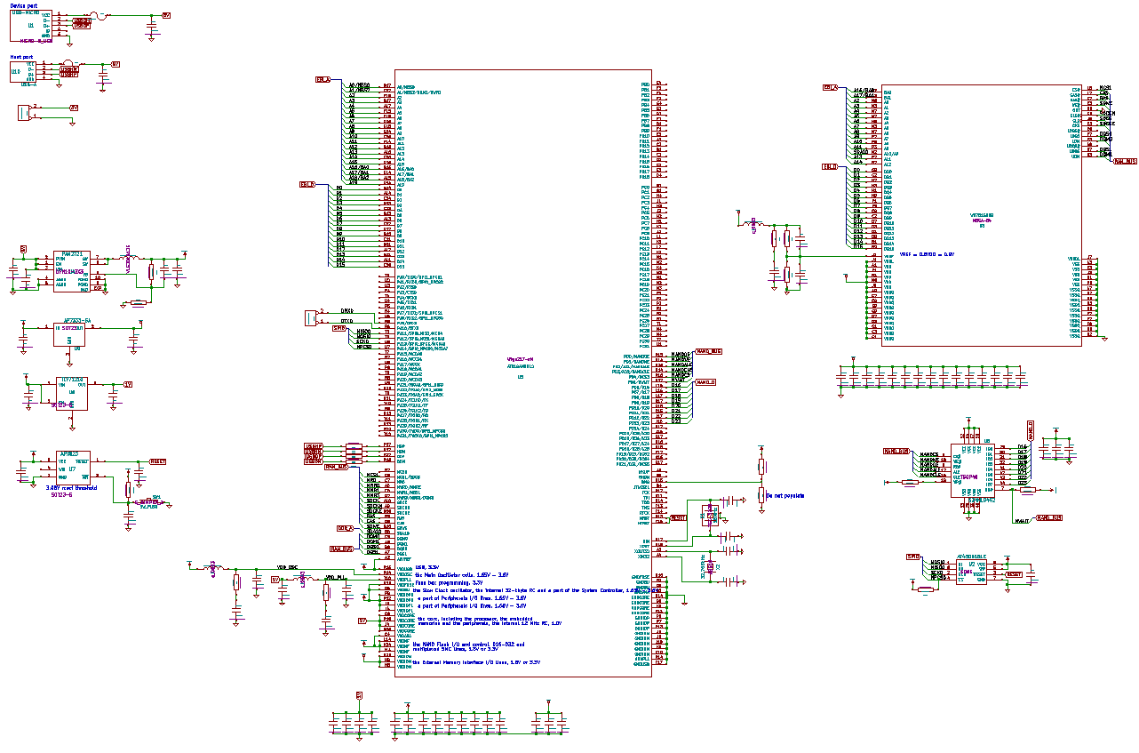
Schematic. Click for a pdf version.
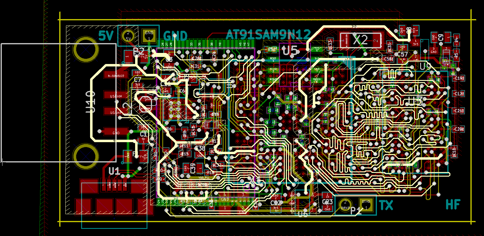
PCB layout. Copper pours are not filled.