Cisco Aironet 2800 Series Access Points, Getting Started Guide
The documentation set for this product strives to use bias-free language. For the purposes of this documentation set, bias-free is defined as language that does not imply discrimination based on age, disability, gender, racial identity, ethnic identity, sexual orientation, socioeconomic status, and intersectionality. Exceptions may be present in the documentation due to language that is hardcoded in the user interfaces of the product software, language used based on RFP documentation, or language that is used by a referenced third-party product. Learn more about how Cisco is using Inclusive Language.
Table of Contents
Getting Started Guide
Cisco Aironet 2800 Series Access Points
About this Guide
This guide provides instructions on how to install your Cisco Aironet 2800I and 2800E series access points and provides links to resources which can help you configure the access point. This guide provides mounting instructions and limited troubleshooting procedures. The 2800 series access point is referred to as access point or AP in this document.
About the Access Point
The Cisco Aironet 2800 Series Wi-Fi access points provide 802.11ac Wave 2 with Multi User MIMO (MU MIMO). This AP series offers integrated and external antenna options, with a dedicated 5 GHz radio and a flexible radio that can be configured as a 2.4 GHz radio (default) or as an additional 5 GHz radio. This access point supports a greater overall High Density Experience (HDX) which provides mission-critical wireless to meet your performance needs. The access points support full interoperability with leading 802.11ac clients, and support a mixed deployment with other access points and controllers. A full listing of the access point’s features and specifications are provided in the Cisco Aironet 2800 Series Access Point Data Sheet, at the following URL: http://www.cisco.com/c/en/us/products/collateral/wireless/aironet-2800-series-access-points/datasheet-c78-736497.html
Access Point Features
The 2800 series access point is a wireless controller-based product and supports: ■Integrated antennas on the 2802I access point model (AIR-AP2802I-x-K9) ■External antennas on the 2802E access point models (AIR-AP2802E-x-K9)
Note The ‘x’ in the model numbers represents the regulatory domain. For information on supported regulatory domains, see theAP Model Numbers and Regulatory Domains.
■Flexible Radio Assignment, allowing for either manual configuration or for the APs to intelligently determine the operating role of the integrated radios based on the available RF environment. The AP can operate in the following modes: –2.4 GHz and 5 GHz role, where one radio serves clients in 2.4 GHz mode, while the other serves clients in 5 GHz mode. –Dual 5 GHz radio role, with both radios operating in the 5 GHz band, actively serving client devices to maximize the benefits of 802.11ac Wave 2 and to increase client device capacity. –Wireless Security Monitoring and 5 GHz role, where one radio serves 5 GHz clients, while the other radio scans both 2.4 GHz and 5 GHz for wIPS attackers, CleanAir interferers, and rogue devices. ■Multiuser Multiple-Input Multiple-Output (MU-MIMO) technology with 3 spatial streams. ■Cross-AP Noise Reduction, a Cisco innovation that enables APs to intelligently collaborate in real time about RF conditions so that users connect with optimized signal quality and performance. ■Optimized AP Roaming for ensuring that client devices associate with the AP in their coverage range that offers the fastest data rate available. ■Cisco ClientLink 4.0 technology for improved downlink performance to all mobile devices, including one-, two-, and three-spatial-stream devices up to 802.11ac Wave 1 and Wave 2. The technology also improves battery life on mobile devices. ■Cisco CleanAir technology enhanced with 160MHz channel support. CleanAir delivers proactive, high-speed spectrum intelligence across 20-, 40-, and 80-, and 160-MHz-wide channels to combat performance problems arising from wireless interference. ■MIMO equalization capabilities, which optimize uplink performance and reliability by reducing the impact of signal fade. The AP supports the following operating modes: ■Local—This is the default mode for the Cisco AP. In this mode, the AP does not serve clients. ■Flexconnect—Flexconnect mode for the Cisco AP. ■Monitor—This is the monitor-only mode for the Cisco AP. ■SE-connect—Spectrum expert-only connect mode allows the AP to perform spectrum intelligence. ■Sensor—Sensor mode for the Cisco AP.
Note The AP can only be configured to Sensor mode if it is an external antenna AP with no DART connected. However, for external antenna APs with DART connected or internal antenna APs, only the dual-band radio can be set to Sensor role. The dual-band radio can operate as a sensor on both the 2.4 GHz and 5 GHz bands. This allows the other radio to serve clients or perform other operations on 5 GHz.
■Sniffer—In the wireless sniffer mode, the AP starts sniffing the air on a given channel. It captures and forwards all the packets from the clients on that channel to a remote machine that runs Airopeek or Wireshark (packet analyzers for IEEE 802.11 wireless LANs). This includes information on the time stamp, signal strength, packet size, etc.
Note In the sniffer mode, the server to which the data is sent should be on the same VLAN as the wireless controller management VLAN otherwise an error will be displayed.
AP Model Numbers and Regulatory Domains
| AP Type | Model Number | Details |
|---|---|---|
| Access Point for indoor environments, with internal antennas | AIR-AP2802I-x-K9 | Dual-band, controller-based 802.11a/g/n/ac |
| Access Point for indoor environments, with external antennas | AIR-AP2802E-x-K9 |
Antennas and Radios
The 2800 series access point contains a dedicated 5 GHz radio and a flexible radio that can be configured as a 2.4 GHz radio (default) or as an additional 5 GHz radio. The 2800 series access point configurations are: ■AIR-AP2802I-x-K9—One 2.4 GHz/5 GHz flexible radio and one 5 GHz radio. ■AIR-AP2802E-x-K9—One 2.4 GHz/5 GHz flexible radio and one 5 GHz radio. The are 4 dual-band dipole and a Smart antenna connector. Internal Antennas The 2802I has 12 cross polarized internal antennas. External Antennas The 2802E model is configured with up to four external dual-band dipole antennas, and two 2.4 GHz/ 5 GHz dual-band radios. The radio and antennas support frequency bands 2400–2500 MHz and 5180–5865 MHz through a common dual-band RF interface. Features of the external dual-band dipole antennas are: ■Four RTNC antenna connectors on the top of the access point ■Four TX/RX antennas ■Smart Antenna connector for connecting an external antenna
Supported External Antennas
| Part Number | Description | Gain |
|---|---|---|
| AIR-ANT2524DB-R/= | Dipole Antenna, Black, with RP-TNC connectors. | 2 dBi (2.4 GHz) 4 dBi (5 GHz) |
| AIR-ANT2524DG-R/= | Dipole Antenna, Gray, with RP-TNC connectors. | 2 dBi (2.4 GHz) 4 dBi (5 GHz) |
| AIR-ANT2524DW-R/= | Dipole Antenna, White, with RP-TNC connectors. | 2 dBi (2.4 GHz) 4 dBi (5 GHz) |
| AIR-ANT2535SDW-R | Low Profile Antenna, White, with RP-TNC connectors. | 3 dBi (2.4 GHz) 5 dBi (5 GHz) |
| AIR-ANT2566P4W-R= | Directional Antenna, 4-port, with RP-TNC connectors. | 6 dBi (2.4 GHz) 6 dBi (5 GHz) |
| AIR-ANT2524V4C-R= | Ceiling Mount Omni Antenna, 4-port, with RP-TNC connectors. | 2 dBi (2.4 GHz) 4 dBi (5 GHz) |
| AIR-ANT2544V4M-R= | Wall Mount Omni Antenna, 4-port, with RP-TNC connectors. | 4 dBi (2.4 GHz) 4 dBi (5 GHz) |
| AIR-ANT2566D4M-R= | 60 Degree Patch Antenna, 4-port, with RP-TNC connectors. 1 | 6 dBi (2.4 GHz) 6 dBi (5 GHz) |
1. For the USA, the UNII-1 channels can be used only indoors.
Safety Instructions

IMPORTANT SAFETY INSTRUCTIONS
This warning symbol means danger. You are in a situation that could cause bodily injury. Before you work on any equipment, be aware of the hazards involved with electrical circuitry and be familiar with standard practices for preventing accidents. Use the statement number provided at the end of each warning to locate its translation in the translated safety warnings that accompanied this device. Statement 1071
SAVE THESE INSTRUCTIONS

This product relies on the building’s installation for short-circuit (overcurrent) protection. Ensure that the protective device is rated not greater than: 20A. Statement 1005
Do not operate your wireless network device near unshielded blasting caps or in an explosive environment unless the device has been modified to be especially qualified for such use. Statement 245B
In order to comply with FCC radio frequency (RF) exposure limits, antennas should be located at a minimum of 12 inches (30 cm) or more from the body of all persons. Statement 332

The fasteners you use to mount an access point on a ceiling must be capable of maintaining a minimum pullout force of 20 lbs (9 kg) and must use all 4 indented holes on the mounting bracket.
This product and all interconnected equipment must be installed indoors within the same building, including the associated LAN connections as defined by Environment A of the IEEE 802.af Standard.
Note The access point is suitable for use in environmental air space in accordance with section 300.22.C of the National Electrical Code and sections 2-128, 12-010(3), and 12-100 of the Canadian Electrical Code, Part 1, C22.1. You should not install the power supply or power injector in air handling spaces.
Note Use only with listed ITE equipment.
Unpacking
To unpack the access point, follow these steps:
Unpack and remove the access point and the accessory kit from the shipping box.
- Return any packing material to the shipping container and save it for future use.
- Verify that you have received the items listed below. If any item is missing or damaged, contact your Cisco representative or reseller for instructions.
–Mounting bracket (selected when you ordered the access point)
–Adjustable ceiling-rail clip (selected when you ordered the access point)
AP Views, Ports, and Connectors
Face of the 2802I Model
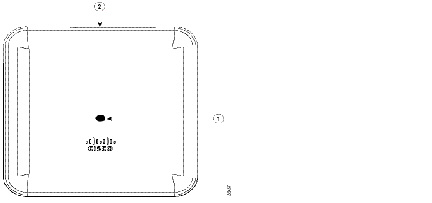
Location of the ports and connectors on the head of the AP.
Face of the 2802E Model
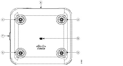
Dual-band antenna connector A
Dual-band antenna connector B
Location of the ports and connectors on the head of the AP
Dual-band antenna connector C
Location of the Smart antenna connector port on the right side of the AP
Dual-band antenna connector D
The ports and connections on the bottom of the access point are shown in Ports and Connectors on the Head of the 2802E Model .