How to configure VLAN and interVLAN Routing in Packet Tracer
Welcome to this tutorial! This is a simple step by step guide of configuring VLAN and interVLAN routing on a Cisco switch. But just before get into configurations , let’s have a brief overview of what’s a VLAN.
What is a VLAN?
A Virtual LAN (VLAN) is simply a logical LAN, just as its name suggests. VLANs have similar characteristics with those of physical LANs, only that with VLANs, you can logically group hosts even if they are physically located on separate LAN segments.
We treat each VLAN as a separate subnet or broadcast domain. For this reason, to move packets from one VLAN to another, we have to use a router or a layer 3 switch.
VLANs are configured on switches by placing some interfaces into one broadcast domain and some interfaces into another. For this tutorial, we’ll configure 2 VLANs on a switch. We’ll then proceed and configure a router to enable communication between the two VLANs.

2. Create 2 VLANs on the switch: VLAN 10 and VLAN 20 . You can give them custom names.
Switch#config terminal Switch(config)#vlan 10 Switch(config-vlan)#name SALES Switch(config-vlan)#vlan 20 Switch(config-vlan)#name IT
3. Assign switch ports to the VLANs. Remember each VLAN is viewed as separate broadcast domain.
And just before you configure, have in mind that switch ports could be either access or trunk .
- An access port is assigned to a single VLAN . These ports are configured for switch ports that connect to devices with a normal network card, for example a PC in a network.
- A trunk port on the other hand is a port that can be connected to another switch or router. This port can carry traffic of multiple VLANs.
So in our case, we’ll configure switch interfaces fa 0/1 through fa 0/4 as access ports to connect to our PCs. Here, interfaces fa 0/1 and fa 0/2 are assigned to VLAN 10 while interfaces fa 0/3 and fa 0/4 are assigned to VLAN 20.
Switch Interface fa0/5 will be configured as trunk port, as it will be used to carry traffic between the two VLANs via the router.
Switch>enable Switch#config terminal Switch(config)#int fa0/1 Switch(config-if)#switchport mode access Switch(config-if)#switchport access vlan 10 Switch(config-if)#int fa0/2 Switch(config-if)#switchport mode access Switch(config-if)#switchport access vlan 10 Switch(config-if)#int fa0/3 Switch(config-if)#switchport mode access Switch(config-if)#switchport access vlan 20 Switch(config-if)#int fa0/4 Switch(config-if)#switchport mode access Switch(config-if)#switchport access vlan 20
Worth noting : We could have configured all the above interfaces as access ports using interface range command as shown below:
Switch(config-if)#int range fa0/1-4 Switch(config-if-range)#switchport mode access
In the above commands, we have specified an interface range and then proceeded to configure all the ports specified as access ports.
Interface fa0/5 is configured as trunk and will be used to for inter-VLAN communication.
Switch(config)#int fa 0/5 Switch(config-if)#switchport mode trunk
4 . Assign static IP addresses to the four PCs which are located in the separate VLANs. PC1 and PC2 fall in VLAN 10 while PC3 and PC4 fall in VLAN 20.
PC1 IP address 192.168.1.10 Subnet mask 255.255.255.0 Default gateway 192.168.1.1
PC2: IP address 192.168.1.20 Subnet mask 255.255.255.0 Default gateway 192.168.1.1
PC3: IP address 192.168.2.10 Subnet mask 255.255.255.0 Default gateway 192.168.2.1
PC4: IP address 192.168.2.20 Subnet mask 255.255.255.0 Default gateway 192.168.2.1
And now it’s very clear that we treat a VLAN just like a physical LAN when assigning IP addresses.
At this point let’s try to test connectivity within VLANs and between VLANs
To test communication between hosts in the same VLAN:
Ping PC2 from PC1 both in VLAN 10. Ping test should be successful.
To test connectivity between hosts in different VLANs:
Ping PC3 in VLAN 20 from PC1 in VLAN 10. Ping here will definitely fail. Why? Because inter-VLAN routing is not yet enabled. Hope you can see how we’ve used VLANs to place the hosts into two logical networks which can be viewed as separate broadcast domains.
Now, in order to allow the hosts in the two VLANs to communicate, we need to do something extra. And you can guess what. We’ll configure the router to permit inter-VLAN communication. Let’s do that right away.
5. Configure inter-VLAN routing on the router
We’ll configure the router so that it will enable communication between the two vlans via a single physical interface. How is this made possible? We’ll divide the single physical interface on the router into logical interfaces (sub interfaces). Each sub-interface will then serve as a default gateway for each of the VLANs. This scenario is called router on a stick (R.O.A.S) and will allow the VLANs to communicate through the single physical interface.
Wort noting : We can’t assign an IP address to the router’s physical interface that we have subdivided into logical sub-interfaces. We’ll instead assign IP addresses to the sub interfaces.
So let’s do router configurations:
Router>enable Router#config terminal Router(config)#int fa0/0 Router(config-if)#no shutdown Router(config-if)#int fa0/0.10 Router(config-subif)#encapsulation dot1q 10 Router(config-subif)#ip add 192.168.1.1 255.255.255.0 Router(config-subif)# Router(config-subif)#int fa0/0.20 Router(config-subif)#encapsulation dot1q 20 Router(config-subif)#ip add 192.168.2.1 255.255.255.0
As you can notice from above, the routers physical interface fa0/0 was subdivided into two sub-interfaces( fa0/0.10 and fa0/0. 20 ) , which are then configured as trunk interfaces and given IP addresses.
6. Test inter-VLAN connectivity .
Here we’ll test connectivity between computers in different VLANs . Don’t forget that its the router that enables inter-VLAN routing.
Ping PC3 in VLAN 20 from PC1 in VLAN 10. If everything is well configured, then ping should work perfectly.
Hope this article was useful to you. Comment to help improve it.
Артём Санников
Данная книга является руководством для начинающих специалистов в области анализа и обработки данных. В книге рассматривается язык SQL и его процедурное расширение PL/SQL от компании Oracle.

Главная › Cisco › Cisco Packet Tracer › Настройка основных параметров маршрутизатора. Cisco packet tracer.
Настройка основных параметров маршрутизатора. Cisco packet tracer.
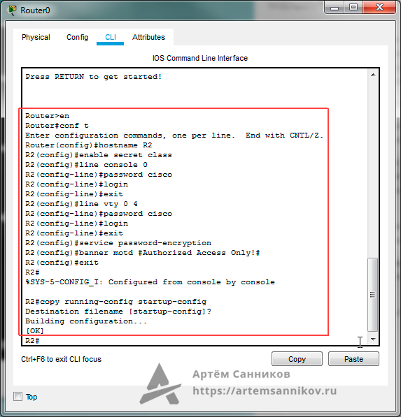
В этом уроке мы выполним настройку основных параметров маршрутизатора (router) в программном обеспечении Packet tracer. Каждая введённая команда сопровождается комментарием.
Router>en // Переходим в привилегированный режим EXEC
Router#conf t // Переходим в режим глобальной конфигурации
Enter configuration commands, one per line. End with CNTL/Z.
Router(config)#hostname R2 // Присваиваем маршрутизатору имя R2
R2(config)#enable secret class // Устанавливаем слово — class, в качестве секретного пароля
// Устанавливаем пароль — cisco, для консольного канала и настраиваем процедуру для входа пользователей.
R2(config)#line console 0
R2(config-line)#password cisco
R2(config-line)#login
R2(config-line)#exit
// Устанавливаем пароль — cisco, для виртуального терминала (VTY) для каналов от 0 до 4, и настраиваем процедуру для входа пользователей
R2(config)#line vty 0 4
R2(config-line)#password cisco
R2(config-line)#login
R2(config-line)#exit
R2(config)#service password-encryption // Выполняем процедуру шифрования всех открытых паролей
R2(config)#banner motd #Authorized Access Only!# // Устанавливаем текст для баннера motd (уведомление о несанкционированном доступе)
R2(config)#exit
R2#
%SYS-5-CONFIG_I: Configured from console by console
R2#copy running-config startup-config // Сохраняем конфигурацию
Destination filename [startup-config]?
Building configuration…
[OK]
Основные параметры для маршрутизатора установлены.
Записи по теме
Артём Санников
Данная книга является руководством для начинающих специалистов в области анализа и обработки данных. В книге рассматривается язык SQL и его процедурное расширение PL/SQL от компании Oracle.
Главная › Cisco › Cisco Packet Tracer › Настройка основных параметров маршрутизатора. Cisco packet tracer.
Настройка основных параметров маршрутизатора. Cisco packet tracer.
В этом уроке мы выполним настройку основных параметров маршрутизатора (router) в программном обеспечении Packet tracer. Каждая введённая команда сопровождается комментарием.
Router>en // Переходим в привилегированный режим EXEC
Router#conf t // Переходим в режим глобальной конфигурации
Enter configuration commands, one per line. End with CNTL/Z.
Router(config)#hostname R2 // Присваиваем маршрутизатору имя R2
R2(config)#enable secret class // Устанавливаем слово — class, в качестве секретного пароля
// Устанавливаем пароль — cisco, для консольного канала и настраиваем процедуру для входа пользователей.
R2(config)#line console 0
R2(config-line)#password cisco
R2(config-line)#login
R2(config-line)#exit
// Устанавливаем пароль — cisco, для виртуального терминала (VTY) для каналов от 0 до 4, и настраиваем процедуру для входа пользователей
R2(config)#line vty 0 4
R2(config-line)#password cisco
R2(config-line)#login
R2(config-line)#exit
R2(config)#service password-encryption // Выполняем процедуру шифрования всех открытых паролей
R2(config)#banner motd #Authorized Access Only!# // Устанавливаем текст для баннера motd (уведомление о несанкционированном доступе)
R2(config)#exit
R2#
%SYS-5-CONFIG_I: Configured from console by console
R2#copy running-config startup-config // Сохраняем конфигурацию
Destination filename [startup-config]?
Building configuration…
[OK]
Основные параметры для маршрутизатора установлены.