Configure A Router With Packet Tracer

Computer networking professionals getting started with Packet Tracer may find the interface to be flustered. Being a development program, this is only natural. However, learning how to configure a router with Packet Tracer will put professionals on the right track to mastering the program in about half an hour.
By this time, you should already have the Packet Tracer download and have it installed on your computer. Open the program and select the router from the lower left-hand corner, and drag it into the center of the sandbox screen as seen below. (Click for larger picture)

We will be setting up a very basic network that allows two computers to communicate, so the next step is to select end devices from the bottom left-hand corner and drag it to the sandbox screen. Do this twice to make two computers appear below the router.
Now select connections from the same bottom left-hand corner. When you connect like-devices(Such as a router and computer) you use a crossover cable, so you should select copper cross-over cable from the second menu to the immediate right. Click on Router0, and connect the cable via FastEthernet0/0 as seen below:

Now click the PC0 and select FastEthernet. You will notice that although a link is established, it is not functional. You can tell by the red dots that are present on both ends of the connection. Once the router is configured correctly, the red dots will turn green to indicate the devices are able to communicate.
Do the same operation to PC1, only this time connect the cable to FastEthernet0/1 since FastEthernet0/0 is already taken by PC0. Your network should be similar to the one below at this point:

Configuring The Router In Packet Tracer
A router that is turned off doesn’t work very well! Click on your router to bring up the configuration menu and verify that it is turned on.When on, there will be a small green light below the switch as seen in the diagram.

Next we have to open the Ethernet ports to allow communication. Although they are physically connected, they are in a state that is known as being in administrative shut down. Now click on the CLI tab to access the configuration menu. If you’ve used the Cisco IOS before, you will notice it looks and acts the same way.
1. Press RETURN to start the session
2. Type enable to get to privileged mode (this gives you more options in configuring the router)
3. Type config terminal (or config t for short) to access the configuration menu.
4. Type interface fastethernet0/0 to access Ethernet0/0
5. Type ip address 192.168.10.1 255.255.255.0 to assign an IP address and subnet mask to the interface.
6. Type no shutdown to open the interface up for business.
That’s it! You should now see a message similar to the following:
%LINK-5-CHANGED: Interface FastEthernet0/0, changed state to up
%LINEPROTO-5-UPDOWN: Line protocol on Interface FastEthernet0/0, changed state to up
Now we have to do the same thing for fastethernet0/1. If you don’t, there still won’t be a connection to PC1! Make sure to enter the IP address carefully as seen below:
1. Press Ctrl + Z to go back to the previous mode.
1. Type interface fastethernet0/1
2. Type ip address 192.168.20.1 255.255.255.0
3. Type no shutdown
At this point our router is configured properly. If you test out a ping, you will notice that the computers still don’t communicate, however!
Configuring The Gateway In Packet Tracer
Our last step is to configure the gateway on each desktop computer. The gateway is the address we assigned to the Ethernet port that the desktop is connected to. It will allow the computer to interface with another network, so our ping won’t work without it!
Click on PC0 to bring up the configuration menu. Under global settings you will find a field for the gateway. Enter the corresponding IP address of the router’s interface, which is 192.168.10.1. Then click the FastEthernet tab on the left column to set the actual computer’s IP address to be on the network. Use 192.168.10.2 for the IP address, and 255.255.255.0 for the subnet mask.

Do the same thing for PC1, only use 192.168.20.1 for the gateway address, 192.168.20.2 for the IP address, and 255.255.255.0 for the subnet mask. You can confirm that your network works by sending out a packet of information from PC0 to PC1, and vice versa. Click the packet icon on the right menu as seen below:

Click on PC0 and then click PC1. On the lower right of the screen you will see a message box that says “Successful.” If it doesn’t, you may have had a syntax error when putting in an IP address or router configuration command. Review your work or ask for help among the community if you are stuck.
Closing Comments
Congratulations! You have a small working network. A real-world application of this very network would be to have two computers connected to the Internet, whereas the router would then be connected to your telecommunications company. (Or what we would call the “cloud”)
More advanced devices and topologies won’t be so easy, but you’re now on the right path to becoming qualified for the CCNA certification exam.
Configure IP address to Router and PC in Packet Tracer
Step1: Open the Cisco Packet Tracer.
Step2: Drag and drop any series of the router from the bottom of the interface into the middle of the working area.
Step 3: Select cable from the bottom of the interface to connect the routers.
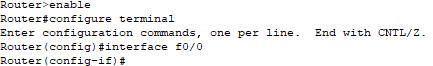
Step 4: Click on Router R0, then on CLI.
Step5: Go to the global configuration mode, and type slot/ port or interface Fast Ethernet 0/0 (or interface f0/0)
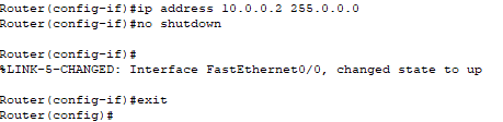
Step 6: Now configure an IP address and subnet mask then give “no shutdown” command. (In our case, IP address is 10.0.0.2 and subnet mask is 255.0.0.0)
Note: Carefully configure IP address with proper interfaces.
Configure an IP Address to Serial Interface
There are following steps involved to configure an IP Address to Serial Interface –
Step1: Open the Cisco packet tracer.
Step2: Drag and drop any series of the router from the bottom of the interface into the middle of the working area.
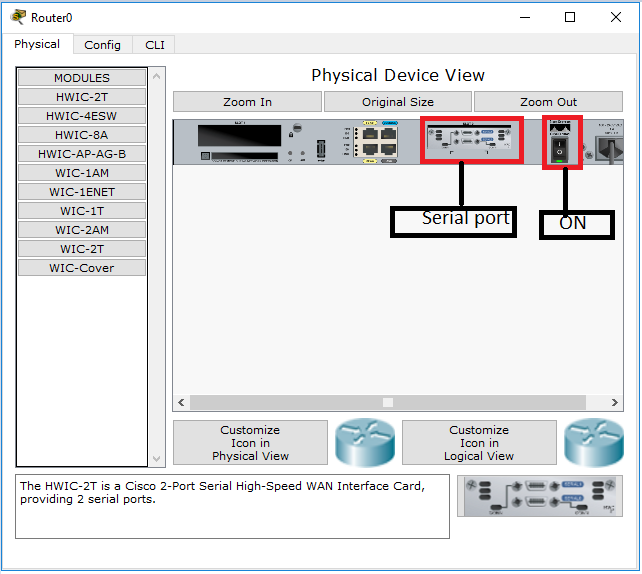
Step 3: Click the Router ->select then Physical->select then WIC-IT->switch off the router.
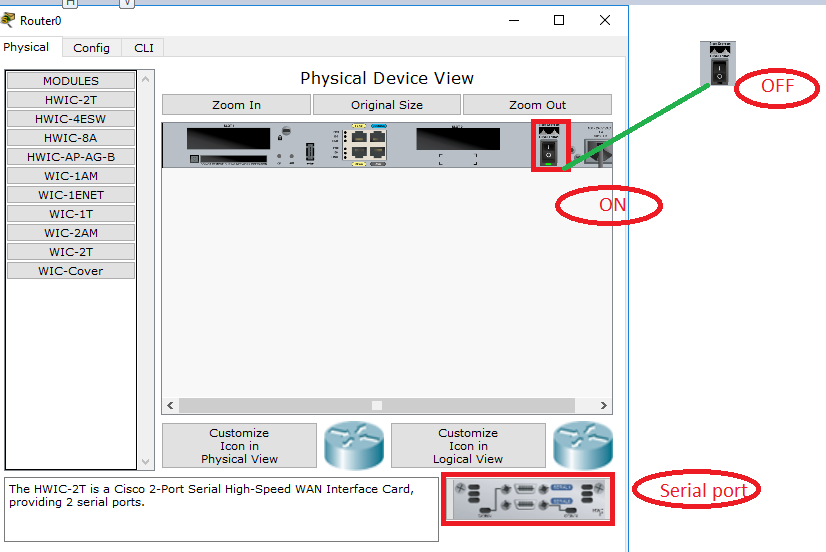
- Add serial port -> Switch ON the router.
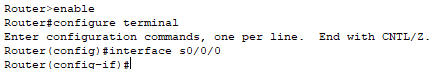
- Now Go to CLI, then the global configuration mode, and type interface serial 0 0/0 (or interface s0/0/0).
- Now, configure an IP address and subnet mask, and then give no shutdown command. (In our case IP address is 10.0.0.2 and subnet mask is 255.0.0.0)
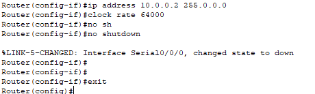
Note: Carefully configure IP address with proper interfaces.
Configure an IP Address to PC
There are following steps involved to configure an IP Address to PC:
Step1: Open the Cisco Packet Tracer.
Step2: Drag and drop PC from the bottom of the interface into the middle of the working area.
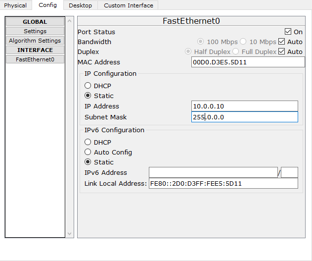
Step3: Click on PC ->Config Gateway like 10.0.0.1
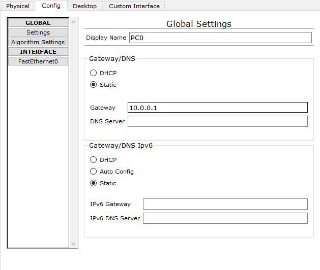
Click on FastEthernet to assign an IP address and subnetmask to the PC, and close PC window. In our case IP is 10.0.0.10 and subnet mask is 255.0.0.0.0,