- Статическая маршрутизация на роутерах Cisco
- Скачать выполненное задание настройки роутера
- Настройка роутера копированием конфигурации
- Configuring Static IP Routing
- Table Of Contents
- Configuring IP Unicast Routing
- Understanding IP Routing
- T ypes of Routing
- I P Routing and Switch Stack s
- S teps for Configuring Routing
- Enabling IP Unicast Routing
- Артём Санников
- Настройка статического маршрута IPv4. Cisco packet tracer.
- Синтаксис команды
- Пример
- Записи по теме
Статическая маршрутизация на роутерах Cisco
В прошлой шпаргалке мы выполнили базовую настройку роутера и назначили IP-адреса интерфейсам роутера («Базовая настройка роутера Cisco»).
Однако (надеюсь Вы помните из готового примера), у нас еще нет возможности отправить удачный пинг в другую сеть (из PC1 к PC3).
Для этого мы и настроим статическую маршрутизацию, которая будет объяснять роутеру где находится другая сеть.
- Устанавливаем консольное соединение через гипертерминал со следующими настройками:
- Скорость: 9600; Биты данных: 8; Четность: Нет; Стоповые биты: 1; Управление потоком: Нет;
- //при входе на роутер вводим пароль — cisco
- R1>enable//Входим в привилегированный режим.
- //вводим пароль — class
- R1#
- R1#configure terminal//заходим в режим глобальной конфигурации
- R1(config)#ip route 172.16.0.0 255.255.255.128 Serial0/0/0//это команда для ввода статического маршрута/ Объясняю вкратце: ip route — это команда, говорящая роутеру, что сейчас будет введен статический маршрут; 172.16.0.0 — это удаленная и неизвестная роутеру сеть; 255.255.255.128 — это маска удаленной сети; serial0/0/0 — это на какой интерфейс слать пакеты, предназначающиеся для той, удаленной сети.
- //помимо вышеназванного способа можно воспользоваться другими командами:
ip route 172.16.0.0 255.255.255.128 192.168.0.194 — в этом случае все тоже самое, только вместо указания интерфейса на какой слать пакеты, указан IP-адрес подключенного интерфейса следующего роутера.
ip route 172.16.0.0 255.255.0.0 Serial0/0/0 — здесь мы увеличили диапазон адресов маской. Теперь на интерфейс уйдут не только пакеты с адресами 172.16.0.1-126, но и 172.16.255.254. Это называется суммированием маршрутов, и заслуживает другой статьи.
ip route 0.0.0.0 0.0.0.0 Serial0/0/0 — а это называется маршрут по умолчанию, т.е. всё, что не предназначается для известных роутеру сетей уйдёт на интерфейс Serial0/0/0. - R1(config-line)#end//выходим в привилегированный режим EXEC Mode
- R1#show running-config//Проверяем введенные данные.
- R1#copy running-config startup-config//Сохраняем произведенную настройку в энерго-независимую память.
Скачать выполненное задание настройки роутера
Предлагаю скачать файл с выполненным заданием для программы эмулятора PacketTracer, открыть его и посмотреть на реализацию. Роутер R2 тоже настроен со статической маршрутизацией, следовательно теперь всё удачно пингуется.
Настройка роутера копированием конфигурации
- Для автоматической базовой настройки (всё, что выше) маршрутизатора выполните следующие действия:
- 1. Скопируйте текст ниже в буфер обмена: выделите всё, кликните правой кнопкой по выделенному и выберите «Копировать».
- 2. При необходимости очистите роутер от всех настроек и перезагрузите его.
- 3. Войдите в режим глобальной конфигурации и вызовите меню Гипер Терминала «Правка», а в нём «Передать главному компьютеру».
- 4. Обязательно проверьте настройки с помощью команды show running-config
- 5. При необходимости включите интерфейсы командой no shutdown из режима каждого интерфейса
Configuring Static IP Routing
The documentation set for this product strives to use bias-free language. For the purposes of this documentation set, bias-free is defined as language that does not imply discrimination based on age, disability, gender, racial identity, ethnic identity, sexual orientation, socioeconomic status, and intersectionality. Exceptions may be present in the documentation due to language that is hardcoded in the user interfaces of the product software, language used based on RFP documentation, or language that is used by a referenced third-party product. Learn more about how Cisco is using Inclusive Language.
Table Of Contents
Configuring IP Unicast Routing
This chapter describes how to configure IP Version 4 (IPv4) stati c IP unicast routing o n the Catalyst 2960-S and 2960 s witch. Static routing is supported only on switched virtual interfaces (SVIs) and not on physical interfaces. The switch does not support routing protocols.
Unless otherwise noted, the term switch refers to a standalone switch and a switch stack. A switch stack operates and appears as a single router to the rest of the routers in the network .
Note Stacking is supported only on Catalyst 2960-S switches.
F or complete syntax and usage information for the commands used in this chapter, see th e C isco IOS IP Command Reference, Volume 1 of 3: Addressing and Services, Release 12. 2
T his chapter consists of these sections:
•Understanding IP Routing
•Steps for Configuring Routing
•Enabling IP Unicast Routing
•Configuring Static Unicast Routes
• Monitoring and Maintaining the IP Network
Note When configuring routing parameters on the switch and to allocate system resources to maximize the number of unicast routes allowed, u se the sdm prefer lanbase-routing g lobal configuration command to set the Switch Database Management (sdm) feature to the routing template. For more information on the SDM templates, see Chapter 8, «Configuring SDM Templates» or see the sdm prefer command in the command reference for this release.
Understanding IP Routing
In some network environments, VLANs are associated with individual networks or subnetworks. In an IP network, each subnetwork is mapped to an individual VLAN. Configuring VLANs helps control the size of the broadcast domain and keeps local traffic local. However, network devices in different VLANs cannot communicate with one another without a Layer 3 device t o route traffic between the VLAN, referred to as inter-VLAN routing. You configure one or more routers to route traffic to the appropriate destination VLAN.
Figure 38-1 shows a basic routing topology. Switch A is in VLAN 10, and Switch B is in VLAN 20. The router has an interface in each VLAN.
Figure 38-1 Routing Topology Example
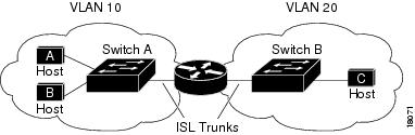
When Host A in VLAN 10 needs to communicate with Host B in VLAN 10, it sends a packet addressed to that host. Switch A forwards the packet directly to Host B, without sending it to the router.
When Host A sends a packet to Host C in VLAN 20, Switch A forwards the packet to the router, which receives the traffic on the VLAN 10 interface. The router checks the routing table, finds the correct outgoing interface, and forwards the packet on the VLAN 20 interface to Switch B. Switch B receives the packet and forwards it to Host C .
T ypes of Routing
Routers and Layer 3 switches can route packets in three different ways:
•By using default routing to send traffic with a destination unknown to the router to a default outlet or destination.
•By using s tatic routes to forward packets from predetermined ports through a single path into and out of a network.
•By dynamically calculating routes by using a routing protoco l.
The switch supports static routes; it does not support routing protocols.
I P Routing and Switch Stack s
Note Stacking is supported only on Catalyst 2960-S switches.
A s witch stack appears to the network as a single switch, regardless of which switch in the stack is connected to a p eer. For additional information about switch stack operation, see Chapter 5, «Managing Switch Stacks.»
The stack master performs these functions :
• T he MAC address of the stack master is used as the router MAC address for the whole stack, and all outside devices use this address to send IP packets to the stack.
•All IP packets that require software forwarding or processing go through the CPU of the stack master.
Stack members perform these functions:
•They act as routing standby switches, ready to take over in case they are elected as the new stack master if the stack master fails.
•They program the routes into hardware.
If a stack master fails, the stack detects that the stack master is down and elects one of the stack members to be the new stack master. During this period, except for a momentary interruption, the hardware continues to forward packets .
A t election, the new stack master performs these functions:
•It starts generating, receiving, and processing routing updates.
•It builds routing tables a nd distributes it to stack members.
•It uses its MAC address as the router MAC address. To notify its network peers of the new MAC address, it periodically (every few seconds for 5 minutes) sends a gratuitous ARP reply with the new router MAC address.
Note If you configure the persistent MAC address feature on the stack and the stack master changes, the stack MAC address does not change for the configured time period. If the previous stack master rejoins the stack as a member switch during that time period, the stack MAC address remains the MAC address of the previous stack master. See the «Enabling Persistent MAC Address» section on page 5-18 .
S teps for Configuring Routing
By default, IP routing is disabled on the switch, and you must enable it before routing can take place. For detailed IP routing configuration information, see the Cisco IOS IP Configuration Guide, Release 12.2 from the Cisco.com page under Documentation > Cisco IOS Software > 12.2 Mainline > Configuration Guides.
In the following procedures, the specified interface must b e a s witch virtual interface (SVI) —a VLAN interface created by using the interface vlan vlan_id global configuration command and by default a Layer 3 interface . A ll Layer 3 interfaces on which routing will occur must have IP addresses assigned to them. See the «Assigning IP Addresses to SVIs» section on page 38-4 .
Note The switch supports 16 user-configured static routes in addition to any directly connected routes and default routes for the management interface. s witch can have an IP address assigned to each S VI. The number of routed ports and SVIs that you can configure is not limited by software. However, the interrelationship between this number and the number and volume of features being implemented might have an impact on CPU utilization because of hardware limitations. Before enabling r outing, enter t he sdm prefer lanbase-routing g lobal configuration command and reload the switch.
C onfiguring routing consists of several p rocedures:
•To support VLAN interfaces, create and configure VLANs on the switch, and assign VLAN membership to Layer 2 interfaces. For more information, see Chapter 14, «Configuring VLANs.»
•Configure Layer 3 interfaces (SVIs).
•Enable IP routing on the switch.
•Assign IP addresses to the Layer 3 interfaces.
• Configure static routes
Enabling IP Unicast Routing
By default, the switch is in Layer 2 switching mode and IP routing is disabled. To use the Layer 3 capabilities of the switch, you must enable IP routing.
Beginning in privileged EXEC mode, follow these steps to enable IP routing:
Use the no ip routing global configuration command to disable routing.
This example shows how to enable IP routing on a switch:
Switch# configure terminal
Артём Санников
Данная книга является руководством для начинающих специалистов в области анализа и обработки данных. В книге рассматривается язык SQL и его процедурное расширение PL/SQL от компании Oracle.

Настройка статического маршрута IPv4. Cisco packet tracer.
Статические маршруты на коммутаторах и маршрутизаторах настраиваются при помощи команды глобальной конфигурации ip route.
Синтаксис команды
- network-address (адрес удалённой сети назначения, который необходимо добавить в таблицу маршрутизации);
- subnet-mask (маска подсети удалённой сети назначения, который необходимо добавить в таблицу маршрутизации);
- ip-address (IP-адрес маршрутизатора для осуществления следующего перехода);
- exit-intf (выходной интерфейс для пересылки пакетов в сеть назначения).
Важно: Для настройки статической маршрутизации необходимо обязательно указывать следующие параметры: netwrok-address и subnet-mask.
Важно: Так же, необходимо использовать один или оба следующих параметров: ip-address и exit-intf.
Пример
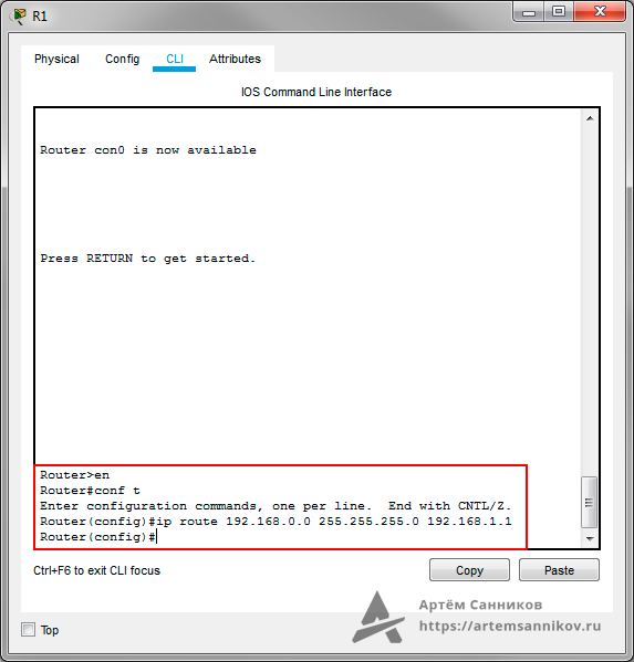
В качестве примера добавим статический маршрут в таблицу маршрутизации на маршрутизаторе.
Router>en // Переходим в привилегированный режим EXEC
Router#conf t // Переходим в режим глобальной конфигурации
Enter configuration commands, one per line. End with CNTL/Z.
Router(config)#ip route 192.168.0.0 255.255.255.0 192.168.1.1 // Указываем путь маршрутизации: удалённая сеть-маска подсети-шлюз соседнего маршрутизатора