- Packet Tracer 7.3 — WLC configuration
- Tutorial introduction
- Cisco WLC 2504 initial setup
- SSID and VLAN configuration on the WLC
- Security configuration using 802.1x
- LightWeight Access Points automatic registration
- Known issues
- Лабораторная работа №5: Cisco Packet Tracer: Wi-Fi (10.05.2018)
- Настройка модели
- Возможно, Вам будет интересно почитать:
- 1 комментарий к “ Лабораторная работа №5: Cisco Packet Tracer: Wi-Fi ”
- WLAN Configuration on Packet Tracer
Packet Tracer 7.3 — WLC configuration
The Cisco Wireless Controller (WLC) devices is the Cisco solution to centrally configure, manage enterprise wireless networks, regardless of the number of access points deployed and thei location. Wireless controllers have become very popular as companies move from standalone Access Point (AP) wireless designs, complicated to configure and to secure properly, to centralized controller-based designs, reaping the enhanced visibility, functionality and redundancy benefits that come with those modern designs.
The following youtube video presents the basic concepts of how Wireless Controllers work and interact with Lightweight access points using CAPWAP protocol. A good understanding of the concepts presented in this video is mandatory before starting this Packet Tracer 7.3 wireless tutorial.

Tutorial introduction
This Packet Tracer 7.3 wireless tutorial will show you how to configure the Wireless LAN controller and the associated Lightweight Access Points embeded in Cisco Packet Tracer 7.3 including :
- WLC 2504 intial setup
- SSID and VLAN configuration on th WLC 2504
- Security configuration using 802.1x
- LightWeight Access Points 3702i automatic registration
This tutorial will be based on the following network topology :

Management IP addressing (Vlan 1 / 192.168.1.0/24)
- Cisco WLC 2504 : 192.168.1.254
- Catalyst L3 switch : 192.168.1.1 (vlan 1 default gateway / DHCP server)
- Management laptop : dynamic IP address from DHCP
- Lightweight Access Points : dynamic IP address from DHCP
Cisco WLC 2504 initial setup
Connect to the WLC 2504 using the web browser of the management laptop using http://192.168.1.254 and configure the admin username and password. The admin credentials will be login: admin, password : P@ssw0rd in this tutorial. Make sure to connect using HTTP (unsecure), not HTTPS, for this first connection.
Packet Tracer 7.1 issue : Access to the web interface can fail several times before allowing showing the following page. It works after a random number of tries.

The second step is to configure time, location, and management IP address of the WLC before creating the first protected Wireless network. Please note that the Guest Network function is not supported in Packet Tracer 7.3 .

After this initial setup, reconnect to the Cisco WLC using HTTPS (https://192.168.1.254). If you try to connect using HTTP (unsecure) the WLC resets the connection but doesn’t automatically redirect the connection to the HTTPS url.
SSID and VLAN configuration on the WLC
WLAN creation and SSID to VLAN mapping is configured on the WLAN tab of the WLC configuration. Each WLAN SSID is associated to a VLAN previously created and linked to a pysical interface on Controller tab. Packet Tracer 7.3 supports the following security options :
- No security
- WPA2 Personal
- WPA2 Enterprise (802.1x)
- Static WEP
- Static WEP + 802.1x
- CKIP
- None + EAP Passthrough

Security configuration using 802.1x
LightWeight Access Points automatic registration
Cisco Lightweight access points are directly connected to the layer 3 Catalyst 3560 switch and are PoE power supplied by the switch, making deployment quite easy. Attention is required for the access switch deployment which needs reduncdant power supplies and suffisant power budget from the closet to power up all the connected WLC.
Switch#show power inline Available:370.0(w) Used:15.0(w) Remaining:355.0(w) Interface Admin Oper Power Device Class Max (Watts) --------- ------ ---------- ------- ------------------- ----- ---- Fa0/1 auto on 5.0 Light Weight Access Point0n/a 15.4 Fa0/2 auto on 5.0 Light Weight Access Point1n/a 15.4 Fa0/3 auto on 5.0 Light Weight Access Point2n/a 15.4
Lightweight Access Points automatically discover the WLC address using DHCP option 150 configured on the DHCP which has been configured on the Catalyst switch for Vlan 1.
ip dhcp excluded-address 192.168.1.1 192.168.1.9 ! ip dhcp pool MGMT network 192.168.1.0 255.255.255.0 default-router 192.168.1.1 option 150 ip 192.168.1.254
The WLC displays thesuccessfully registered Access Points with thir IP address. detailed data is not available as this function has not been implemented in Packet Tracer 7.1

Known issues
When configuring the WLC port to trunk mode and applying a static IP to the WLC, connection to the management interface of the WLC fails. The issue has been identified by Cisco and it’s correction has been integrated in Packet Tracer 7.1.1
Packet Tracer crashes when configuring DHCP on WLC-PT wireless controller. Issue will be corrected in Packet Tracer 7.2
Legal
Video tutorial «Fundamentals of Wireless Controllers » is extracted from Youtube and subject to the following youtube terms of service :
8.1 When you upload or post Content to YouTube, you grant:
- to YouTube, a worldwide, non-exclusive, royalty-free, transferable licence (with right to sub-licence) to use, reproduce, distribute, prepare derivative works of, display, and perform that Content in connection with the provision of the Service and otherwise in connection with the provision of the Service and YouTube’s business, including without limitation for promoting and redistributing part or all of the Service (and derivative works thereof) in any media formats [and through any media channels];
- to each user of the Service, a worldwide, non-exclusive, royalty-free licence to access your Content through the Service, and to use, reproduce, distribute, prepare derivative works of, display and perform such Content to the extent permitted by the functionality of the Service and under these Terms.
Лабораторная работа №5: Cisco Packet Tracer: Wi-Fi (10.05.2018)
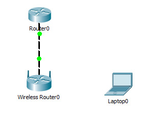
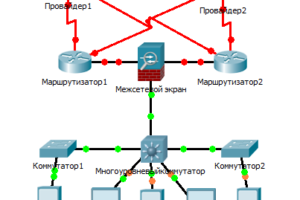
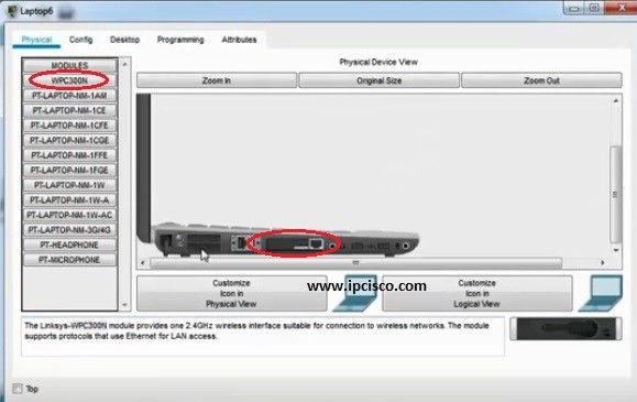
Создать модель локальной сети, состоящей из обычного домашнего wi-fi роутера и маршрутизатора, который имитирует провайдера Интернета. Использовать интерфейс Fast Ethernet. Добавим ещё пользовательское устройство, например ноутбук. Установим модуль wi-fi (WPC300N) в ноутбук.
Настройка модели
1)Настройки маршрутизатора провайдера Router0 (жирным выделено то, что необходимо ввести с клавиатуры:
Router>en
Router#
Router#conf t
Enter configuration commands, one per line. End with CNTL/Z.
Router (config)#int fa0/0
Router (config-if)#ip address 210.210.0.1 255.255.255.252
Router (config-if)#no shutdown
Router (config-if)#
%LINK-5-CHANGED: Interface FastEthernet0/0, changed state to up
%LINEPROTO-5-UPDOWN: Line protocol on Interface FastEthernet0/0, changed state to up
Router (config-if)#end
Router#
%SYS-5-CONFIG_I: Configured from console by console
Router#wr mem
Building configuration.
[OK]
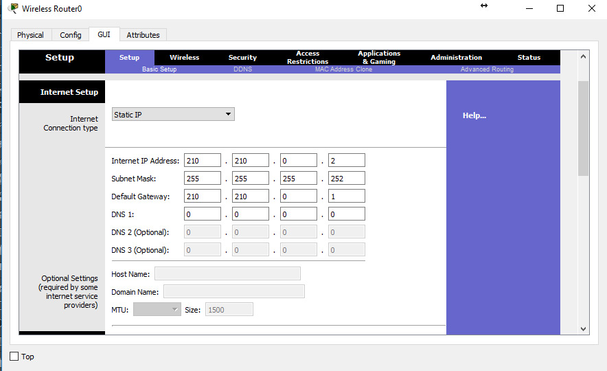
2)Настройки домашнего wi-fi маршрутизатора Wireless Router0
выполняется с помощью веб интерфейса.
Настройка внешнего интерфейса во вкладке Setup показана на рисунке.
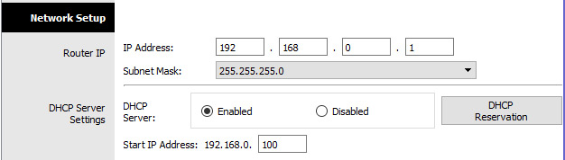
Настройка локальной сети (Network Setup)
Выбираем по умолчанию ip-адрес 192.168.0.1, маска 24-битная 255.255.255.0, разрешён DHCP-сервер, начало раздачи с адреса 192.168.0.100 и всё. После чего незабываем сохранить настройки, нажать на кнопку внизу формы Save Settings.
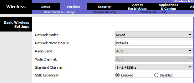
Настройки во вкладке Wireless, т.е. wi-fi. Выбираем основные настройки вайфая: режим (mode), мы выбираем смешанный (mixed); идентификатор сети (SSID) — netskills; ширина канала (Radio Band) — auto; частоту — 1-2.412HGz; видимость сети (SSID Broadcast) — видимая (enable). Сохраняем настройки.
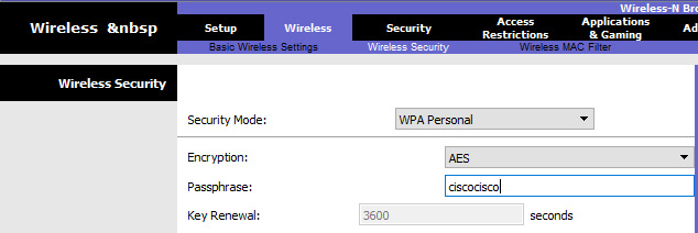
Переходим ко вкладке Wireless Security. Выбираем режим шифрования WPA2 Personal, алгоритм шифрования AES, ключевое слово для выбранного режима шифрования не менее 8 символов. Сохраняем.
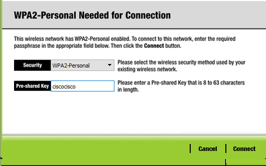
3)Настройка wi-fi адаптера на ноутбуке. Вкладка Desktop->PC Wireless->Connect. Смотрим доступные нам сети. Нажимаем кнопку Connect для подключения к сети netskills.
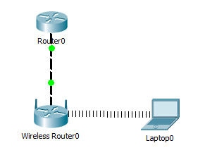
Если настройки произведены верно, то появиться пунктирная линия между wi-fi маршрутизатором и ноутбуком как на рисунке.
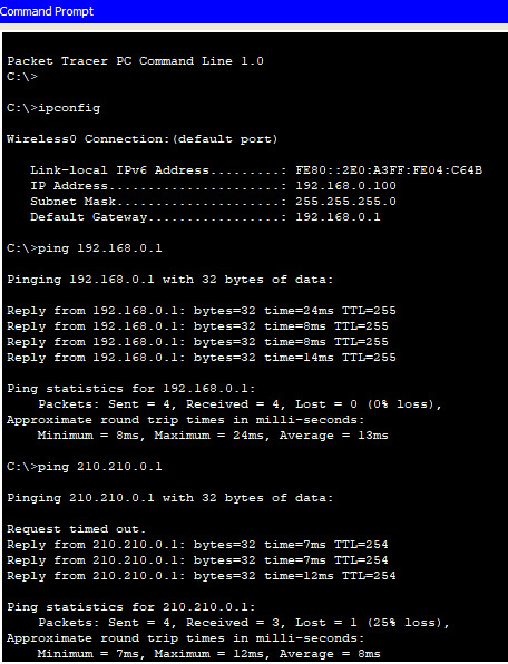
Введём на ноутбуке в командной строке команду ipconfig, чтобы проверить правильность настроек. Из рисунка видно, что DHCP- сервер присвоил правильный ip 192.168.0.100 Пропингуем шлюз (wi-fi маршрутизатор) и пропингуем адрес интернет провайдера. На рисунке видно, что в обоих случаях пинг идёт.
При этом NAT мы не использовали, так как практически на всех wi-fi маршрутизаторах NAT используется по умолчанию.

Если у вас возникли трудности с выполнением задания, вы всегда сможете найти толкового исполнителя здесь: work-zilla.com
Кол-во просмотров: 52989
Возможно, Вам будет интересно почитать:
1 комментарий к “ Лабораторная работа №5: Cisco Packet Tracer: Wi-Fi ”
WLAN Configuration on Packet Tracer
WLANs (Wireless LANs) are very common in today’s World. Everywhere there are a lot of wireless networks. Even now, you are in many of these wireless signals. It is not an healthty life but they are in our lives. In this lesson we will focus WLAN Packet Tracer Configuration and we will learn How to Configure a WLAN on Packet Tracer.
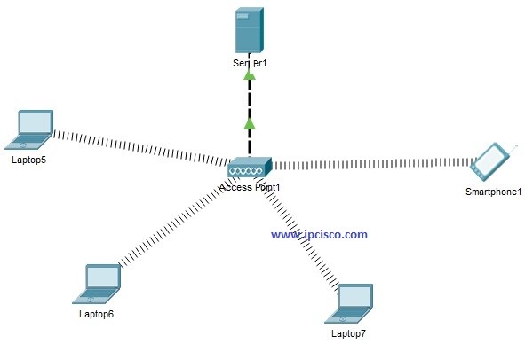
For Our WLAN Configuration on Packet Tracer, we will use the below topology that is consist of one One Wireless Access Point, One Server , Three Laptops and One Smartphone. Smartphones are everywhere, even in Cisco Packet Tracer for many years : )
You can reach all Cisco packet tracer config files on Cisco Packet Tracer Lab Page.
Now, let’s sumamrize what will we do for Packet Tracer WLAN Configuration :
- Place Wireless Interface Card to Laptops
- IP Check on WLAN Devices
- DHCP Server Configuration
- IP Check on WLAN Devices again
Place Wireless Interface Card to Laptops
By default laptops has classic Ethernet card. To involve in a wireless network, we should have wireless interface card. So, in each laptop, we should turn off the laptop, remove the classical Ethernet, instead of it we place Wireless Interface Card (WPC300N). Then, we power on the laptop again.
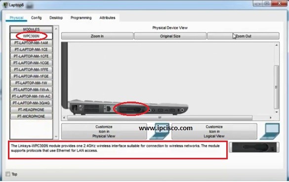
After this processi each laptop connects to th wireless Access Point in Packet Tracer. Smartphone devices in Packet Tracer connects to Access Points (AP) by default. So, there is nothing to do on them.
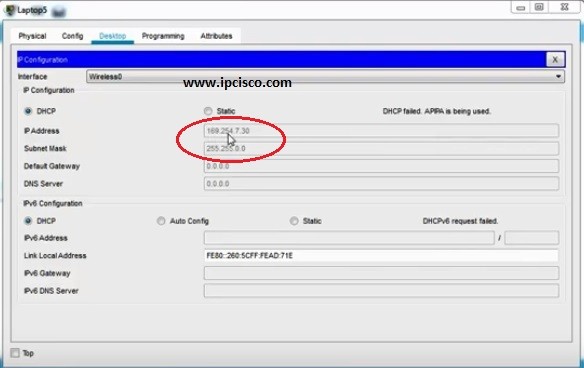
IP Check on WLAN Devices
We will check the IPm addresses of the laptops. For now, chekcing only one of them is enough. Because, at the beginning if there is no Static IP Configuration and no DHCP, an IP from a special block is assigned to the devices. This is APIPA (Automatic Private IP Addressing) addresses. These addresses are from the block “169.254.x.x/25”. Simple, when we say this type of IP address in a device, we can say that it has no IP address.
DHCP Server Configuration
In this step, we will configure our DHCP Server in the WLAN. This server will give IP addresses to our devices who are connected to the Access Point.
In the Services tab of Server, we will go through the DHCP at the left hand. In here, we will define our IP Pool. For this configuration example our DHCP Pool’s name is “IPCisco Pool”. Beside, we will configure the Default Gateway, DNS Server IP addresses. After that we will configure the starting IP and Subnet Mask. DHCP server will start IP asssignition with this IP. And for this example, we have created 254 IP for our IP Pool. We also assign this value on this screen.
After this configuration, we should not forget to “on” our DHCP Service at the top and then, we add our DHCP Pool to the configuration with “add” button.
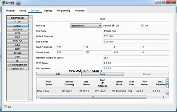
After DHCP Services configuration on DHCP Server, we will configure one more thing on this DHCP Server. This is the IP address and subnet mask of the Server. Here, our Servr IP address will be 172.16.0.1 and the mask will be 255.255.255.0.