- Моделирование электронных схем
- EAGLE Layout Editor
- EasyEDA
- gEDA
- Gneural Network
- gschem
- KiCad
- Meterbridge
- Qucs
- TkGate
- Программа для создания принципиальной электрической схемы на Mac Windows и Linux
- Самая популярная программа для создания принципиальной электрической схемы на Mac Windows и Linux
- Программа для создания принципиальной электрической схемы на Mac Windows и Linux
- Векторные символы для схем
- Как создать принципиальную электрическую схему
- Встроенные примеры принципиальной электрической схемы
- Ваша лучшая программа для создания принципиальной электрической схемы на Mac Windows и Linux!
- Top 10 Circuit design tools for Linux
- What are your goals?
- What is your current level?
- KiCAD
- QUCS – SPICE
- Fritzing
- PCBmodE – Inkscape
- Xschem
- tkgate
- simulide (simavr)
- gnucap (gspiceui)
- caneda
- Conclusion
- About the author
- Mats Tage Axelsson
Моделирование электронных схем
Circuit Diagram — программа для создания (рисования) принципиальных схем и последующего сохранения их в формате PNG или SVG.
EAGLE Layout Editor
Приложение для разработки и проектирования печатных монтажных плат, широко используемых как в радиоэлектронике, так и в компьютерной технике.
EasyEDA
Oблачная платформа для рисования и симуляции схем, разводки печатных плат и прочее.
gEDA
gEDA — это набор инструментов для разработки электронных схем.
Состоит из программы схемотехнического моделирования, генератора таблиц соединений, модуля проверки символов, и ряда утилит.
Gneural Network
В рамках проекта Gneural Network развивается система моделирования работы нейронной сети, подходящая для решения задач машинного обучения.
gschem
gschem – программа для разработки принципиальных схем электротехнических устройств — редактор схем (Schematic capture), разработки Ales Hvezda.
KiCad
Приложение для разработки электрических схем и печатных плат.
Meterbridge
Визуализаторы сигнала воспроизводящие облик аналоговых измерителей уровня.
Qucs
Qucs (Quite Universal Circuit Simulator — Целиком Универсальный Симулятор Цепей) — программа для симулирования всех видов электрических цепей с графическим QT интерфейсом.
TkGate
TkGate — это управляемая событиями программа моделирования электронных схем с графическим редактором, основанным на TCL/Tk. Поддерживает широкий диапазон простейших электронных компонентов, также определенные пользователем модули для многоуровневой разработки.
Что почитать?
Программа для создания принципиальной электрической схемы на Mac Windows и Linux
Самая популярная программа для создания принципиальной электрической схемы на Mac Windows и Linux
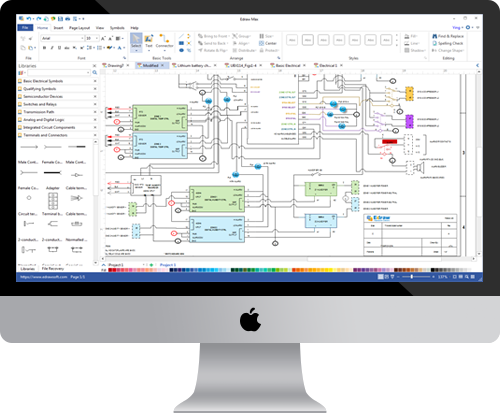
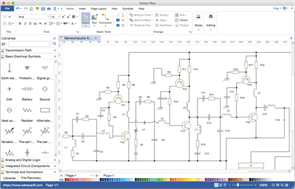
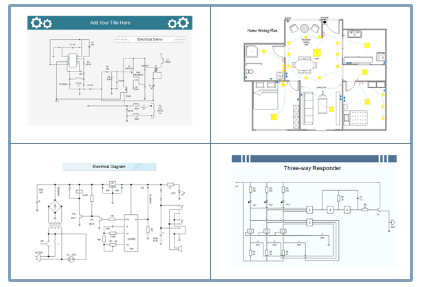
Программа для создания принципиальной электрической схемы с огромной коллекцией символов электрических схем позволяет пользователям создавать профессиональные принципиальные электрические схемы на Mac Windows и Linux.
Программа для создания принципиальной электрической схемы на Mac Windows и Linux
Программа для создания принципиальной электрической схемы — Edraw предоставляет вам быструю, эффективную и умную платформу, которая позволяет каждому,даже новичкам быстро создавать принципиальные электрические схемы с профессиональным внешним видом. Это кросс-платформенная программа, и она работает на Mac и Windows. Вы можете использовать его как альтернатива Visio для создания принципиальной электрической схемы, но его цена на много дешевле, чем Visio.
Векторные символы для схем
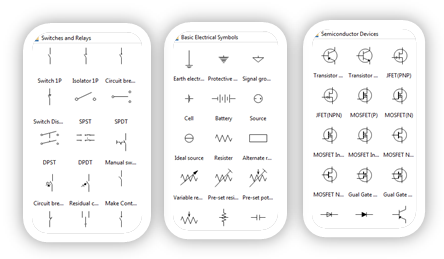
У нас есть 20 коллекций и более 800 электрических символов и элементов в программе, которые охватывают практически все распространенные компоненты для принципиальной электрической схемы. Вы можете найти полные списки резисторов, полупроводников, конденсаторов, переключателей и реле, источников, батарей и т.д. Эти символы изменяемые. Вы можете изменить форматы по вашему желанию.
Как создать принципиальную электрическую схему
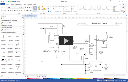
Создать принципиальную электрическую схему при помощью готовых символов и изменить её в нужный Формат через 1 нажатии. Edraw позволяет вам легко закончить схему путем перетаскивания встроенных элементов. Это является быстрым, простым и надежным способом.Благодаря простому интерфейсу и удобным функциям программы, даже новичок сможет создать принципиальную схему в течение нескольких минут.
Встроенные примеры принципиальной электрической схемы
Перед созданием схемы, многие люди хотят смотреть некоторе хорошие примеры. Наша программа также включает в себя примеры, которые вы можете использовать в качестве исходных шаблонов. Мы также рекомендуем пользователям поделиться своими отличными дизайнами в разделе электрических схем нашего сообщества.
Ваша лучшая программа для создания принципиальной электрической схемы на Mac Windows и Linux!
Получите удовольствие от создания принципиальной электрической схемы с полнофункциональной программой. Вы будете удивлены её изобильными символами и шаблонами! Вы будете изумлены её лёгкой работой! Вы будете довольны её услугой и ценой! Попробуйте её именно сегодня!
Top 10 Circuit design tools for Linux
So, you are planning a new electronics project and wonder what tools are the best? You may also be learning to design your own circuits and your favourite platform is Linux. Where are the Linux specific, or cross-platform tools, and which one suits my needs the best? Today, you will learn what you need to get started with your new project. This list goes through the tools available and discusses the pros and cons of each. You will also hear about how they specialise.
What are your goals?
Before you start, you may want to consider what your current goals are. Are you learning to create hobby projects or are you already bringing your game to a higher level? You may also want to consider if your favourite electronics supplier already supports the tool you are going to make. Many of these tools import catalogues to the application so you can browse while designing, making it very convenient to order boards or components.
What is your current level?
Your goals need to align with your current skills. If you are reading the basics, you are going to need a system that shows more information about the circuits. It should also help you with the tasks. The basic systems are text based, a beginner do not want to start that way. Fortunately, many programs are very instructive and you can even simulate your circuits.
Let’s get started. In the list, you will find all levels of interaction and help you can get right now. Some are even command line, so you can use a terminal.
KiCAD
The KiCAD program has many nice introduction features and a nice interface. You can pick a template from an impressive list. The list includes Raspberry Pi, Arduino projects and also BeagleBone. There is a vibrant community contributing new templates, libraries and components to the GitHub repository. You can download the latest or track the repository yourself. The template format is a text file that you can write yourself also, though it may take some time to get used to handling the parenthesis.
The interface is clear and easy to use. The package is split in many parts so you edit one thing at a time. You end up editing the project, the PCB and the schematic in different windows. It covers all the parts of the process, including simulating your circuits to make sure you have not made any dangerous mistakes in your design.
You have export functions to netlist, pcb and other formats. Import functions include EAGLE files netlist and many more. KiCAD is a well rounded package with many features and an active community that is willing to help.
QUCS – SPICE
Qucs-S is first and foremost a simulator, you can make schematics and you have some components but the focus is on the simulation. This tool is a nice graphic interface to NGspice, XYCE or SpiceOpus, you can choose which one you want to use as you start it. Once the software is running, you can see the focus on academics. You have many components and creating a circuit is fairly simple but you can also insert probes and equations. There are many import and export functions, you can also create pictures of your schematics.
The focus on academics is obvious on the homepage, where you have links to users scientific publications using Qucs-S. This package also requires that you have the simulator software on your system before you start. You can also see how there are many ways to probe the system you have created. You also have the equations available for controlling the simulation.
All this means that you should use Qucs-S to learn the basic theories and to research how components and systems work. you have no way of creating a circuit board nor ordering components. In short, you need more packages for manufacturing.
Fritzing
Fritzing is actually a non-profit company that sells electronics and kits for education. The software is clear and well made, it has more colour and icons for the components. As the software is intended for education, it is very clear and helpful. Included in the default install, you have many components from the catalogues of SparkFun. To add components, you pick them from a list on the side and drag and drop them to your project.
The interface has an interesting twist in that you, by default, have a breadboard view of your circuit. You can easily switch to a schematics view or a PCB. When you switch to the PCB view you have both auto-routing functions and manual capability. It also handles many layers. The switching between views makes it a breeze to make plans for a breadboard and then transition into a PCB. You can also order the PCB from the File drop-down menu in the application.
Fritzing has no support for simulation so you need to use other software for that. To do that, you export as a SPICE file and import in the simulator software. You can read more about it in this article.
PCBmodE – Inkscape
PCBmodE is a script that takes an SVG file and output JSON files to create Gerber files. The workflow for this system is a bit more text based. You need to create the JSON file by hand, let PCBmodE create an SVG file and then edit them in InkScape. Then you can take out the changes in InkScape again.
The package is not that advanced and cannot simulate or check the routes. The real reason to use this package is when you want an odd shape of your board. You should really create and test the board with other tools and use PCBmodE for the artistic point of view.
Xschem
Xschem is a schematic editor that requires a bit more in depth knowledge to run. It is great for creating schematics and has nice library of components. When you use it, it shows links to simulators and other programs but it needs everything installed separately. It is useful as a front end to these other tools. You cannot use it to order components. You have many keyboard shortcuts to learn and you need to install the other programs. When you have done that, you have a great package to work with.
tkgate
Tkgate is a digital circuit simulator. It is limited to digital circuits but it does that very well. The best feature of this package is the multitude of very clear tutorials that run in the application. The simulation module can handle many different scenarios when it comes to logic. It also has a way to follow the circuit through a timeline.
This software works well if you are planning to do only digital components. You have only standard components and cannot make PCB boards directly with this package.
simulide (simavr)
The simulide software is aimed specifically at simulating and testing circuits. You can make schematics using drag and drop. Included in the components are voltage meters, Ampere Meters and oscilloscopes. You also have buttons, potentiometer, wave generator and a clock.
This software is easy to use and can give you a good idea how your circuit will work. The designers are not promising great precision, instead they aim at ease of use. You can not use it to make circuit boards or route wires. It is in early stages of development and does not support export to other formats.
gnucap (gspiceui)
The gnucap software is command line completely. You should use this package to learn about the SPICE files. The Gnucap homepage has nice tutorials. If you follow them, you know the basics of the file format. This is useful, if not necessary, to keep top of any odd behaviour in all these software packages. Using it for making circuits is not a good idea.
caneda
Caneda is an old software that still works but has not been maintained for several years. It is easy to make schematics and simulate according to the ngspice method. It has symbol libraries but there is no intuitive way to plan PCB production.
Conclusion
There are many choices of circuit related tools. You need to decide for yourself which one you need for your project and current situation. Some tools can support you the whole way to a running board, some, you need to make many different steps to achieve that. You may just want a small part of the possibilities. It is all up to you.
About the author
Mats Tage Axelsson
I am a freelance writer for Linux magazines. I enjoy finding out what is possible under Linux and how we can all chip in to improve it. I also cover renewable energy and the new way the grid operates. You can find more of my writing on my blog.
