- External antenna modifications for the Raspberry Pi 3
- Overview:
- Top mount:
- U.FL Connector:
- Performance:
- Future Work:
- Внешняя антенна для малинки PI3B+ на Wanhao D7+
- Подпишитесь на автора
- Raspberry pi wifi антенна внешняя
- Re: Raspberry Pi 4 External Wifi Antenna
- Re: Raspberry Pi 4 External Wifi Antenna
- Re: Raspberry Pi 4 External Wifi Antenna
- Re: Raspberry Pi 4 External Wifi Antenna
- Re: Raspberry Pi 4 External Wifi Antenna
External antenna modifications for the Raspberry Pi 3
This post will detail a couple of different ways that an external antenna can be added to the Raspberry Pi 3.
DO NOT TRY THIS AT HOME. ALL OF THE FOLLOWING WILL HAPPEN:
1) YOU WILL VOID YOUR WARRANTY
2) YOU WILL VIOLATE FCC REGULATIONS
3) THE PI’S WI-FI CERTIFICATION WILL BE VOID
IN ADDITION, YOU COULD EASILY DAMAGE YOUR PI
Please view this as a purely experimental exercise and proceed at your own risk.
It’s not clear why an external antenna is not an option for the Pi 3, there are a number of possible reasons and I don’t presume to know the Raspberry Pi Foundation’s exact rationale. It could be to improve the out-of-box experience, an integrated antenna «just works» and there’s no potential for the antenna connector to be broken plugging in an antenna. It could be to reduce complexity, the unit with an integrated antenna is compact and self-contained. It could be for regulatory reasons: in order to sell the device for use with a user-supplied antenna, the performance characteristics of that antenna need to be specified as part of the user instructions, and those characteristics must be adhered to in order to maintain compliance. Good luck with that.
Overview:
There are two basic approaches to adding a connector for an external antenna: remove the onboard antenna on the top side of the board and solder a coaxial pigtail in its place, or use the supplied pads on the bottom side and mount a U.FL connector. The first approach is much easier and can likely be accomplished with few special tools aside from a good soldering iron; however it results in compromised performance. The second approach involves precision soldering and is best attempted with strong magnification and a very fine soldering iron tip. Do not attempt it unless you’re comfortable working with 0201 components (0.020″ by 0.010″, about the width of two and a half human hairs). It does result in substantially improved performance as compared to the top mount approach.
Top mount:
Start by removing the onboard antenna. Soldering tweezers or a heat gun can be used, or a well-tinned soldering iron with a sufficiently large tip. After removal, the board will look like this:
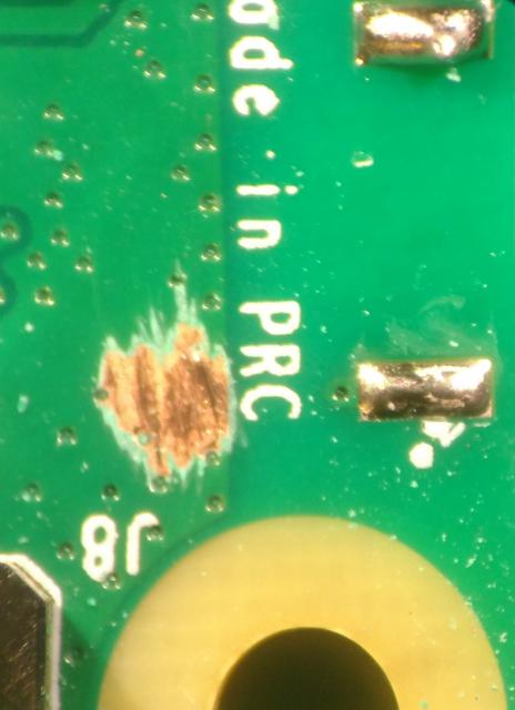
Note that some soldermask will need to be cleared away to attach the coax’s shield, as seen to the left in the image. Next, prepare the coax tail. Strip the outer insulation back ~0.150″ (3.75mm), tin the shield, then trim the shield back about 0.100″ (2.5mm), finally, strip the center conductor about 0.050″ (1.25mm) from the end. Solder the shield to the groundplane, and the center conductor to the antenna feed pad. The finished result will look like this:
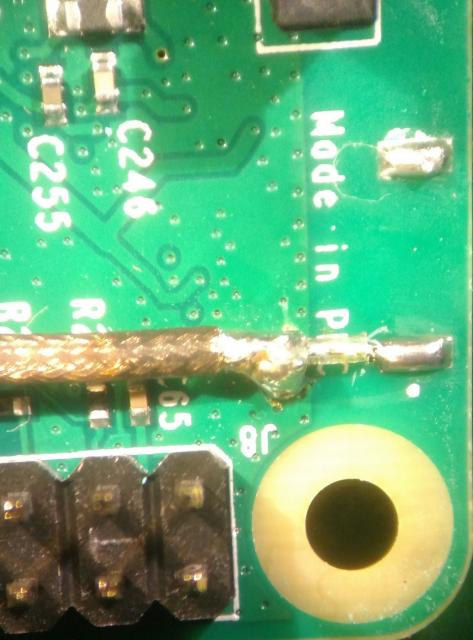
The finished product, with coaxial «tail» attached will look like ths:
U.FL Connector:
Mounting a U.FL connector to the board is straightforward for those with experience working with miniscule surface mount devices. It involves clearing some soldermask and rotating one zero-ohm resistor.
Here is a U.FL connector overlaid on the provided pads:
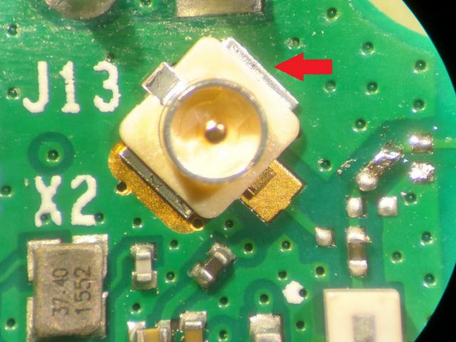
Note that while the U.FL connector fits very well on the two exposed pads, there’s soldermask covering the area where one of the leads falls. While you could just solder the two exposed pins, for mechanical robustness and optimal RF performance it’s best to clear out that solder mask and solder the lead. After mounting the U.FL, rotate the resistor nearest the output filter, the large white device in the bottom of the image, 45 degrees to the left. The result will look like this:
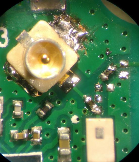
Be careful not to short ground to the header pin just above the connector.
Another approach would be to cut the output trace leading to the antenna and add a solder blob to bridge the output trace to the trace leading to the U.FL connector. I haven’t tried this, but I don’t see any reason it wouldn’t work, though likely with some adverse impact on the RF performance.
Performance:
After completing the steps in that procedure and rebooting, I was able to connect to the Pi with my Android phone. Using a spectrum analyzer with an attached rubber duckie antenna, I was able to observe the AP beacon packets being transmitted. I captured the transmitted beacon spectrum at channels 1, 6, and 11 (2412, 2437, and 2462 MHz), then moved on to conducted measurements.
I observed the conducted output power of the Pi using a Tektronix MDO4000-series mixed-domain oscilloscope, using an RF power trigger on the beacon packets. Power measurements were calibrated to an HP 8481D power sensor. The observed RF output powers are shown below:
| Channel | Frequency | Coaxial tail output power | U.FL output power |
|---|---|---|---|
| 1 | 2412 MHz | 14.13 dBm | 15.98 dBm |
| 6 | 2437 MHz | 13.67 dBm | 16.15 dBm |
| 11 | 2462 MHz | 13.47 dBm | 16.39 dBm |
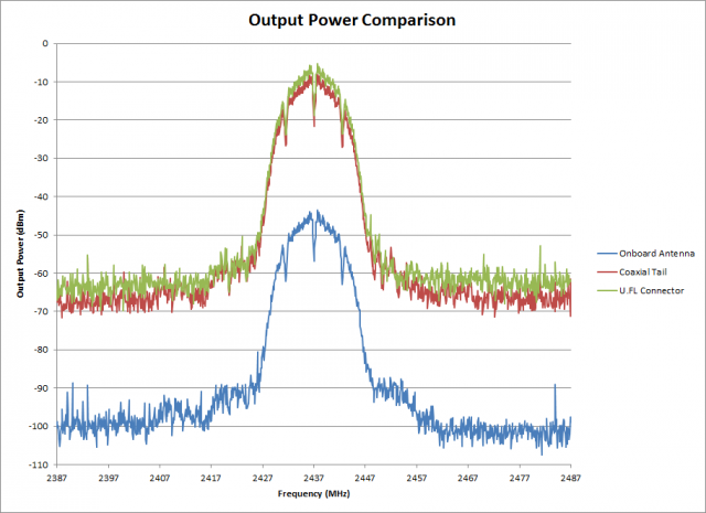
The U.FL numbers are consistently 2-3 dBm higher, almost a doubling in conducted power at the high end of the band. This is due to the massive impedance discontinuities presented by the antenna feed trace and the exposed center conductor of the coaxial cable. While it’s likely possible to recoup some of that with RF tuning using the series and shunt placements in the RF path, at that point it makes more sense to go to the U.FL connector approach. A comparison of the output spectra is shown below, with no compensation applied (hence the radiated power is much lower than the conducted powers). All graphs use a resolution bandwidth of 10 kHz.
A normalized graph showing the relative spectral regrowth is below.
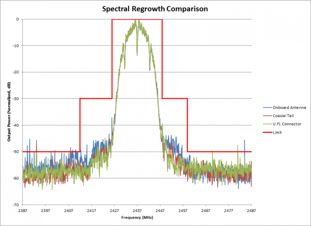
This graph is useful for comparing the in-band noise performance of the various approaches. The onboard antenna fares the worst close-in to the carrier, likely due to either fundamental mismatch or poor harmonic termination impacting power amplifier linearity. Further out the spectra become more comparable. The violating spikes are transient in nature, not part of the modulated waveform. Also, the resolution bandwidth used here is incorrect, it should be 100 kHz for 802.11 spectral mask measurement.
Future Work:
No attempt has been made to characterize out-of-band performance, or performance with any particular make or model of external antenna. A more comprehensive review of spurious and harmonic emissions is advised. Also, while it’s likely that the U.FL and coaxial cable approaches lead to satisfactory WLAN performance, further analysis of adjacent channel power and error vector magnitude would be wise.
Внешняя антенна для малинки PI3B+ на Wanhao D7+
Подпишитесь на автора, если вам нравятся его публикации. Тогда вы будете получать уведомления о его новых статьях.
Отписаться от уведомлений вы всегда сможете в профиле автора.
Статья относится к принтерам:
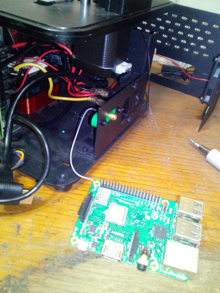
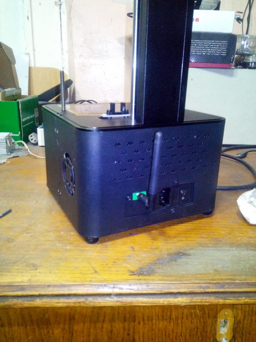
У меня стоит малинка с операционной системой Mang’Os, где есть возможность общаться с принтером и кидать ему файлы для печати по Wi-Fi, без необходимости в разъёме USB, этот шнур был удалён и вот технологическое отверстие осталось а зияет как дырка, хоть и находится с задней части корпуса.
По мере эксплуатации ОС выяснилось, что малинка по WI-FI очень плохо ловит точки доступа, если те установлены не рядом а иногда и телефон лежащий подле с трудом находит, не зависимо от частот принимаемого сигнала. Оно и понятно т.к. плата «заключена» в железном кейсе.
Разъём со шнуром был выпаян из старого роутера, была смоделирована заглушка на которой будет держаться разъём, деталюшка распечатана на FDM. Ну пардоньте, что было заправлено в принтер то и есть, мне цветовая гамма «штанов» не критична.
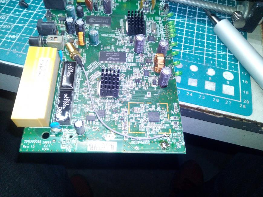
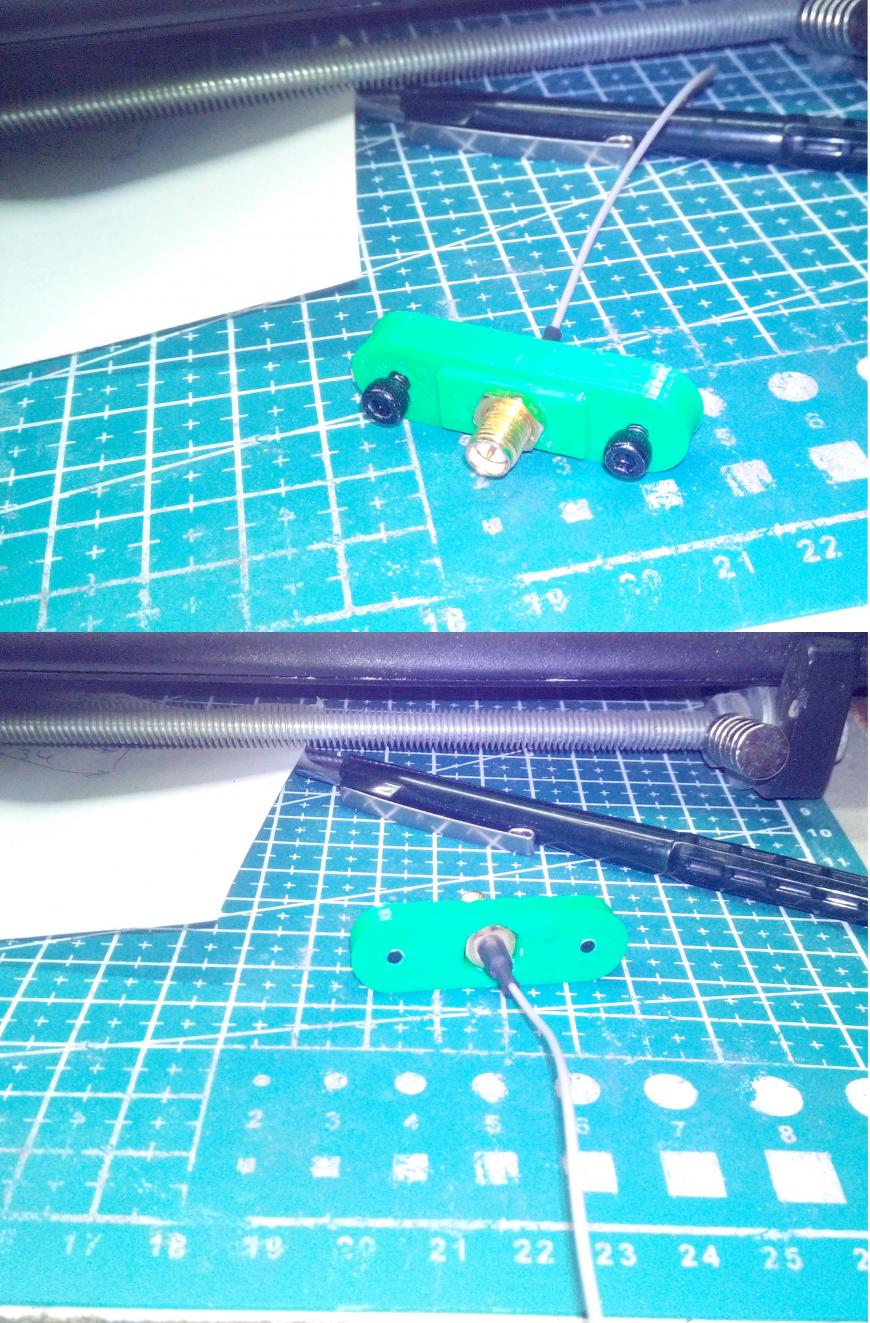
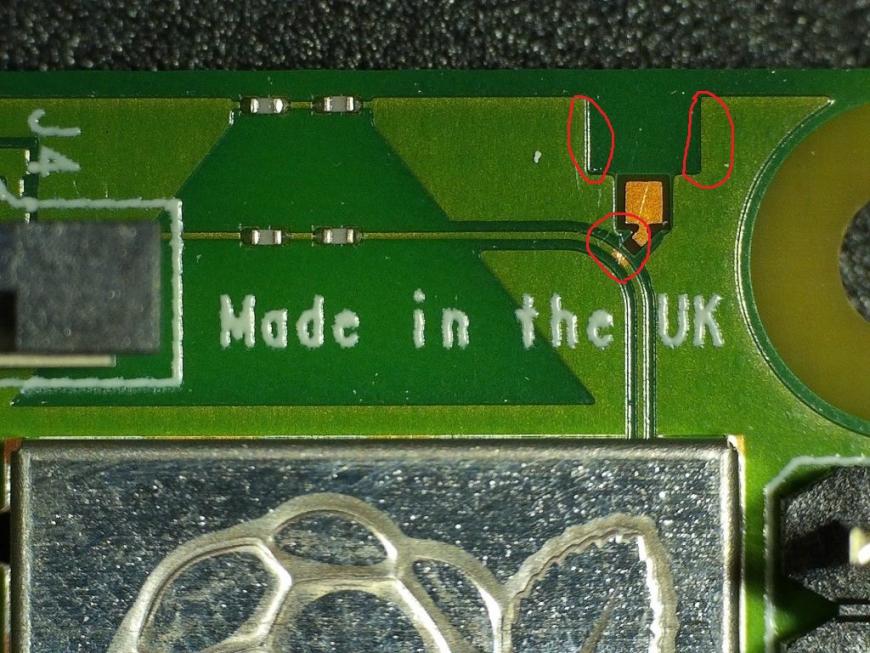
Порывшись в нете выяснилось, где на плате место куда припаивать разъём(ооочень маленькое место), но у меня его нет, надо просто припаять провод в это место.
Верхние отметки, эти места надо зачистить от лака, краски, еcли решили устанавливать разъёмом(снаружи папа внутри мама), в моём случае залудить можно только одну сторону. На нижней отметке нужно соединить дорожку с площадкой(повесить соплю), я припаялся на прямую к дорожке(зачистил дорожку дальше и залудил). Резисторы(по моему), которые на плате с лева я не стал трогать, пусть и старая антенна(супер-пупер керамическая) тоже будет задействована, как оказалось в моём случае в дальнейшем, на скорость не влияет.
Пластиковая заглушка-разъём встала как родная.
После сборки и теста малинка стала видеть точки, которые просто не видела, уверенно и быстро соединяется, держит связь в двух диапазонных частот.
P.S. Общаясь с разработчиком Mang’Os(не коммерческая операционка для D7, D7+) заявил, что в этом году выпустят релиз и люди могут ей свободно пользоваться, с апреля месяца в ОС многое изменилось и поменялось(отдельная тема). У французов растут коммерческие проекты а не коммерческие плетутся в хвосте.
Подпишитесь на автора
Подпишитесь на автора, если вам нравятся его публикации. Тогда вы будете получать уведомления о его новых статьях.
Отписаться от уведомлений вы всегда сможете в профиле автора.
Raspberry pi wifi антенна внешняя
The Raspberry Pi 4 apparently has a transmit power of 31.00 dBm which could be used for long range WiFi using a directional antenna.
So in order to add a connector on the RPi 4 what would I need to buy and do?
jahboater Posts: 8708 Joined: Wed Feb 04, 2015 6:38 pm Location: Wonderful West Dorset
Re: Raspberry Pi 4 External Wifi Antenna
You could buy a USB Wifi adapter, many of which have an SMA socket so you may choose the antenna.
You can’t modify the Pi (it may not even be legal).
bensimmo Posts: 6175 Joined: Sun Dec 28, 2014 3:02 pm Location: East Yorkshire
Re: Raspberry Pi 4 External Wifi Antenna
They’ll not advise you on here (legal reasons), nor will actual methods be discussed a lot.
But if you search for it you’ll find how.
It is the same method used on the 3B+ as it has the same layout.
davidcoton Posts: 7040 Joined: Mon Sep 01, 2014 2:37 pm Location: Cambridge, UK
Re: Raspberry Pi 4 External Wifi Antenna
You could buy a USB Wifi adapter, many of which have an SMA socket so you may choose the antenna.
You can’t modify the Pi (it may not even be legal).
Further, modifying the Pi will invalidate CE and FCC approvals, and any remaining warranty. Go the USB adapter route.
EDIT: clarified what is potentially illegal and what is permitted.
Re: Raspberry Pi 4 External Wifi Antenna
Where did you find the spec saying Pi4B has 31dBm transmit power? However,
By modifying any radio device its EU or FCC approval will most likely loose validity. When buying a radio with an antenna connector, you are allowed to change the antenna in effect and will not loose approval.
With a directional antenna you have to reduce the transmit power depending on related limits of the frequency band used. You have to strictly stay below a limit of Equivalent Isotropically Radiated Power EIRP. Equivalent radiated power is not the same as transmit power.
In effect, 31 dBm transmit power of the Raspberry is not the outstaning property targeting a No 1 choice as a long range WIFI device. In case you’d succeed attaching a 20 dB gain higly directional antenna you had to bring down the Pi’s transmit power down to 10dBm in order to maintain the EIRP limit of 30dBm for selected 5GHz bands or to even lower 0dBm in the 2.4GHz band.
If you already know what EIRP is and what you are doing with directional antennas, proceed. Despite loosing any approval, you most likely will not radiate something, that’s beyond the very scope of any approval — except for too much radiation.
In any other case, spend your time reading about transmit power, equivalent isotropically radiated power, antenna gain first.
Re: Raspberry Pi 4 External Wifi Antenna
All forgetting one thing. And it’s something not generally known. If Notupus is a licensed Amateur radio operator. He could go on channel 1 (2.4GHz) setup a MESH node and transmit 1.5Kw (the max allowed). Possible (yes), Probable (not)
All of the above would require modification of the PI, and he would be responsible for everything being in compliance to license.
I always thought the antenna on PI’s since the 3 was inadequate. Diversity antenna systems have always been the norm when you want to hear and be heard. The best way to do it would be to separate the 2.4 and 5GHz as two different paths. Allowing specially tuned antenna’s (directional opt).