- Android Mobile Phone Controlled Bluetooth Robot using AVR Microcontroller
- How to Connect Bluetooth Module to the AVR
- Description
- HC 05 Bluetooth Pinout
- Features
- How to Configure Bluetooth Controller App
- Робот на Arduino, управляемый по Bluetooth со смартфона
- Ссылки на уроки по L298N и Bluetooth модулю
- Описание робота
- Инструкция по сборке робота
- Control a robot car based on esp32 by Bluetooth
- Construction of a robot car based on the ESP32 board controlled by Bluetooth:
- Necessary components
- L298N Module :
- Module d’alimentation 3,3V/5V
- 2 wheel car robot kit
- Assembly
- Micropython program
Android Mobile Phone Controlled Bluetooth Robot using AVR Microcontroller
Controlling a robot car wirelessly is very interesting for a beginner or new in the robotics field. But the main question is how to make a robot car?. In this tutorial, we will cover how to make an android controlled robot car.
For this project, we have two sections. One is transmitter and second is a receiver. Here transmitter is an android phone and connected with the receiver robot using the bluetooth connection. Android phone already has inbuilt bluetooth. To connect to this android bluetooth, we are using one bluetooth module to the receiver side. We pair both the bluetooth module.
After pairing the android phone and robot, we use android application to control the receiver robot. We are using the Bluetooth Controller app to control the android robot. When a forward button is pressed ‘A’ is sent via this android bluetooth to the receiver bluetooth module. Same with other buttons. At the receiver, we write the code to accept the character ‘A’ and move the robot forward. Each button assigned a value, which is known by the receiver. And receiver takes action according to the value received.

Before using the app, we need to configure the application.
How to Connect Bluetooth Module to the AVR
We have used HC-05 bluetooth module for this project. This module is connected with the atmega8. Both the module is connected using the serial communication. This android bluetooth robot using the serial communication to communicate with the bluetooth module and AVR ATmega8.
For an understanding of the serial communication, you can visit our tutorial Arduino Serial Communication Tutorial
Description

The hc-05 bluetooth module has six pins Vcc, GND, RX, TX, Key and State. By default, it comes as a slave device means it will only receive the signal can’t initiate a connection.But if you want to send something from this module then we need to change it to the master mode by applying some AT commands. If we are connecting HC 05 with the android phone we simply use it in Slave Mode. The default transfer rate will be 9600 baud rate. The HC-05 module has a factory set pin “1234” which is used for pairing to the phone.
HC 05 Bluetooth Pinout
Features
- Protocol: Bluetooth Specification v2.0+EDR
- Frequency: 2.4GHz ISM band
- Modulation: GFSK
- Emission power: ≤4dBm, Class 2
- Speed: Asynchronous: 2.1Mbps(Max) / 160 kbps, Synchronous: 1Mbps/1Mbps
- Sensitivity: ≤-84dBm at 0.1% BER
- Power supply: +3.3VDC 50mA
- Security: Authentication and encryption
- Working temperature: -20 ~ +75 Centigrade
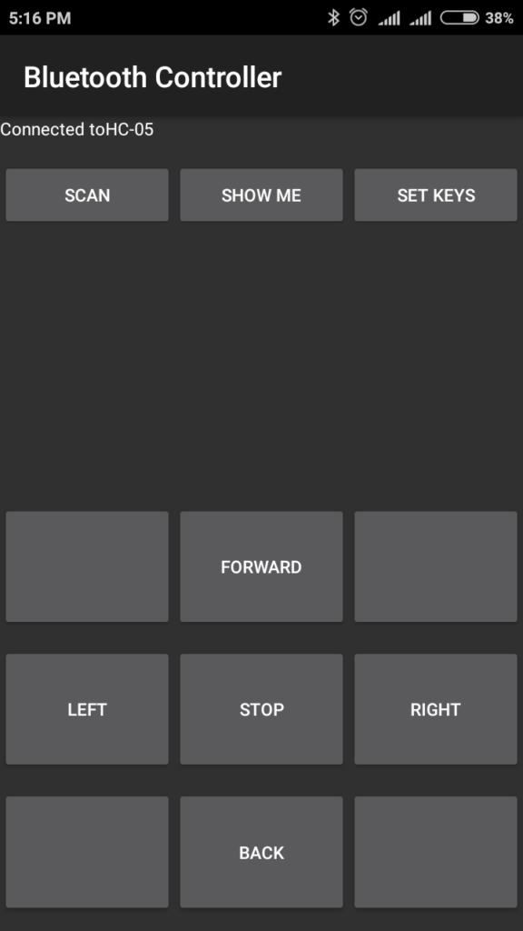
How to Configure Bluetooth Controller App
You can see easily that all the button is blank and we can give a text to this button according to our project.

So press button “SET KEYS”
A new window will open:
Key Name: Forward, Back, Left, Right and Stop => This is Button Text
Key Value: => A, B, C, D and E respectively, Now press OK.


Now connect the bluetooth module as shown above and then supply it. Pair the HC-05 device with the mobile. It is just like we pair the other mobiles. The passkey is “1234”. Once paired we can find it from the bluetooth controller app by pressing the button “SCAN”.

And it’s Done! Now we write the code to AVR that will control the robot by accepting the value A, B, C, D, and E.
Робот на Arduino, управляемый по Bluetooth со смартфона
Всем привет! Сегодня я покажу вам как создать робота, управляемого по Bluetooth со смартфона. В этом уроке использованы:
1. Плата Arduino Uno с кабелем для подключения к компьютеру
2. Компьютер с установленной Arduino IDE и драйверами для плат
4. Драйвер двигателей L298N
5. Bluetooth модуль HC-05 или HC-06
8. Аккумуляторы 18650 2 штуки и бокс для них
Ссылки на уроки по L298N и Bluetooth модулю
Вот ссылки на мои уроки по Bluetooth модулю и драйверу L298N:
Описание робота
Корпус робота, двигатели и электронные компоненты я взял из набора «Мобильные роботы на базе Arduino». Натолкнулся я на этот набор когда ещё только начал заниматься Arduino. Помню, как провозился целый месяц, чтобы робот наконец-то начал слушаться смартфона))) Заказать его можно как в некоторых интернет магазинах, так и на официальном сайте . Вместе с набором идут компоненты для сборки роботов, о которых я расскажу в своих дальнейших статьях.
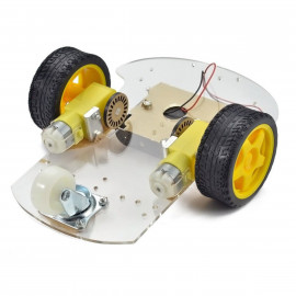
Вот как выглядит робот из набора (извиняюсь за качество фото, лучше сделать не могу):
Робот имеет четыре мотора с четырьмя колёсами. Управляться он будет со смартфона с помощью программы Bluetooth RC Controller, о которой я уже писал в статье про Bluetooth модуль. Давайте же приступим к написанию программы для нашего робота, но сначала нужно его собрать.
Инструкция по сборке робота
Вот инструкция по сборке робота из набора (листайте по стрелочкам):
Control a robot car based on esp32 by Bluetooth
A robot car is a type of autonomous vehicle that is equipped with sensors, software, and other technologies to enable it to navigate and drive itself without human intervention. These types of vehicles are also sometimes referred to as self-driving cars, autonomous cars, or driverless cars. They have the potential to transform the way we travel and could potentially revolutionize transportation as we know it.
A robot car that is equipped with Bluetooth technology would be able to connect to other devices via Bluetooth, allowing it to communicate and transfer data wirelessly. This could be used for a variety of purposes, such as receiving instructions or updates from a remote device, or sending sensor data back to a central computer.
Construction of a robot car based on the ESP32 board controlled by Bluetooth:
The ESP32 is a microcontroller that is often used to build Internet of Things (IoT) devices, as it has built-in WiFi and Bluetooth capabilities. It could potentially be used to build a robot car that is controlled via Bluetooth from a remote device.
To do this, the ESP32 would need to be programmed to receive commands via Bluetooth and translate them into actions for the robot car. For example, the ESP32 could be programmed to move the car forward, backward, left, or right in response to certain commands received over Bluetooth.
The specific steps for building such a robot car would depend on the desired functionality and the available components. Some things to consider might include the type of motors to use for propulsion, how to integrate sensors for navigation and obstacle avoidance, and how to power the device.
Our objective of this project is to produce a robot car controlled by Bluetooth.
Necessary components
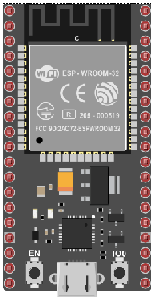
An ESP32 card is a physical device that includes an ESP32 microcontroller and associated components, such as memory and input/output (I/O) pins. These cards are typically designed to be easily integrated into a project or prototype, and can be plugged into a breadboard or other prototyping platform.
ESP32 cards are often used in Internet of Things (IoT) projects, as the ESP32 microcontroller has built-in WiFi and Bluetooth capabilities, making it well suited for connecting to the internet and communicating with other devices wirelessly. These cards may also include additional features such as sensors, OLED displays, or other components that can be used in a project.
L298N Module :
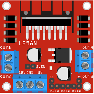
The L298N is a dual H-bridge motor driver IC that is commonly used to control the speed and direction of small DC motors, as well as to drive stepper motors. It can also be used to control the speed and direction of larger motors, such as those found in electric vehicles, by using external power MOSFETs.
The L298N has a number of input and output pins that can be used to control the motors and monitor their status. It can be driven by a microcontroller, such as an Arduino, or by other digital logic devices. The L298N can be used to drive motors in both forward and reverse directions, and the speed of the motors can be controlled by adjusting the duty cycle of the control signals.
Module d’alimentation 3,3V/5V
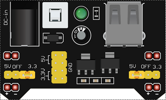
A 3.3V/5V power supply module is a device that converts a higher voltage power source, such as a battery or wall adapter, into a regulated 3.3V or 5V output voltage. These modules are commonly used to provide power to electronic circuits and devices that require a stable, low-voltage power supply.
2 wheel car robot kit
A 2-wheel car robot kit is a collection of components that can be used to build a small, autonomous robot that moves on two wheels. These kits typically include a microcontroller, such as a ESP32 card, to control the robot’s movements, as well as motors, wheels, and other hardware to enable the robot to move and navigate.
2-wheel car robots are often used as educational tools, as they can be used to teach basic principles of robotics, electronics, and programming. They can also be used as a platform for experimenting with different control algorithms, sensors, and other hardware.
This robot kit is composed of:

A test plate is a type of device used in robotics to test the functionality and performance of various components or systems. It is typically a physical platform or structure that is designed to hold and support various test items or devices, such as sensors, actuators, motors, or other types of mechanical or electrical components. Test plates can be used to simulate different environments or conditions, such as temperature, humidity, vibration, or other factors, in order to evaluate the performance of the components or systems being tested. They can also be used to perform a variety of diagnostic or diagnostic tests, such as stress testing, endurance testing, or other types of evaluations.
connecting wires

Wires are used to transmit electrical signals and power to various components such as motors, sensors, and microcontrollers. It’s important to properly route and secure the wires to prevent tangles and damage. There are several methods for doing this, including using cable ties, clamps, and wire looms. It’s also a good idea to use different colors or labeling to identify the different wires and their functions. When connecting wires in a robot, it’s important to follow proper safety procedures, such as using the correct wire stripper and connectors, and wearing protective equipment such as gloves and safety glasses.
Assembly
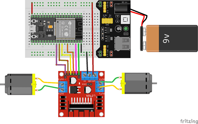
To carry out the assembly it is necessary to connect:
- Connect pin 23 of the ESP32 board to the ENA pin of the L298N module.
- Connect pin 22 of the ESP32 board to pin IN1 of the L298N module.
- Connect pin 21 of the ESP32 board to pin IN2 of the L298N module.
- Connect pin 19 of the ESP32 board to pin IN3 of the L298N module.
- Connect pin 18 of the ESP32 board to pin IN4 of the L298N module.
- Connect pin 5 of the ESP32 board to pin ENB of the L298N module.
- Connect pin GND of the ESP32 board to pin GND of the L298N module.
- Connect the 5V pin of the ESP32 board to the 5v pin of the power supply module
- Connect the GND pin of the ESP32 board to the (-) terminal of the power supply module
- Connect the 12V pin of the L298N module to the 5V pin of the power supply module
- Connect the two motors of the car to the L298N board
Micropython program
Here is the micropython program which allows to control the car by the Smartphone