- Serial-to-WiFi Tutorial using ESP8266
- Usage
- Testing the module via FTDI (or a USB-to-Serial cable)
- Hardware setup
- Software and testing:
- Webserver example:
- Troubleshooting:
- Testing the module via a microcontroller
- Делюсь опытом ESP8266 Wifi Serial Bridge
- WiFi-UART Serial Bridge Using ESP8266 or ESP32
- Prepare The Software
- Prepare The Hardware
- Serial Bridge Using ESP8266 (Simpler)
Serial-to-WiFi Tutorial using ESP8266
The ESP8266 is a low cost Serial-to-WiFi module that interfaces nicely to any microcontroller. However, a word of caution — it is highly undocumented (primary reason for writing this document), and more importantly, it is frequently updated and not backward compatible. A good example is how newer versions use 9600 baud rate, while older versions (by old I’m referring to 2-3 months old modules) used 57600-115200 baud rates.
In general, the tutorial below will get you started. Once you are set up, you should learn more about the module’s protocol here: https://nurdspace.nl/ESP8266#AT_Commands
Usage
First, it is important to understand how the board works. The ESP8266 has a full TCP/UDP stack support. It can also be easily configured as a web server. The module accepts commands via a simple serial interface. It then responds back with the operation’s outcome (assuming everything is running correctly). Also, once the device is connected and is set to accept connections, it will send unsolicited messages whenever a new connection or a new request is issued.
Testing the module via FTDI (or a USB-to-Serial cable)
Before connecting the module to a microcontroller, it’s important to try it directly via a serial interface. An easy solution is to use a 3V3 FTDI cable. Note that the module is not designed for more than 3.6V, so a 3.3V power supply should be used — both for power and logic. The current batch of the FTDI cables deliver 5V in the supply rail even for the 3V3 version. Apparently, this is an error made by the manufacturer, so it might be corrected at some point.
Hardware setup
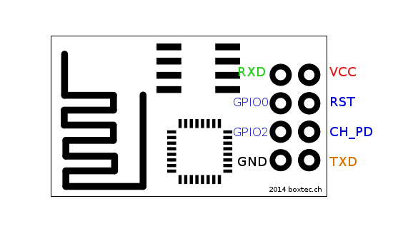
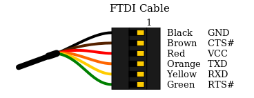
- Connect the RX/TX pins in a 3v3 FTDI cable to the TX/RX pins in the ESP module.
- Connect a 3v3 power supply to the VCC/GND pins. Note that it is possible to use an Arduino 3v3 supply for this.
- Connect the CH_PID pin to VCC as well.
- The rest of the pins should be floating. However, be prepared to occasionally ground the RST pin. This would help if the board is stuck on some command.
Software and testing:
- Clone this repository: https://github.com/guyz/pyesp8266
- Unzip and execute the following command: python esp8266test.py
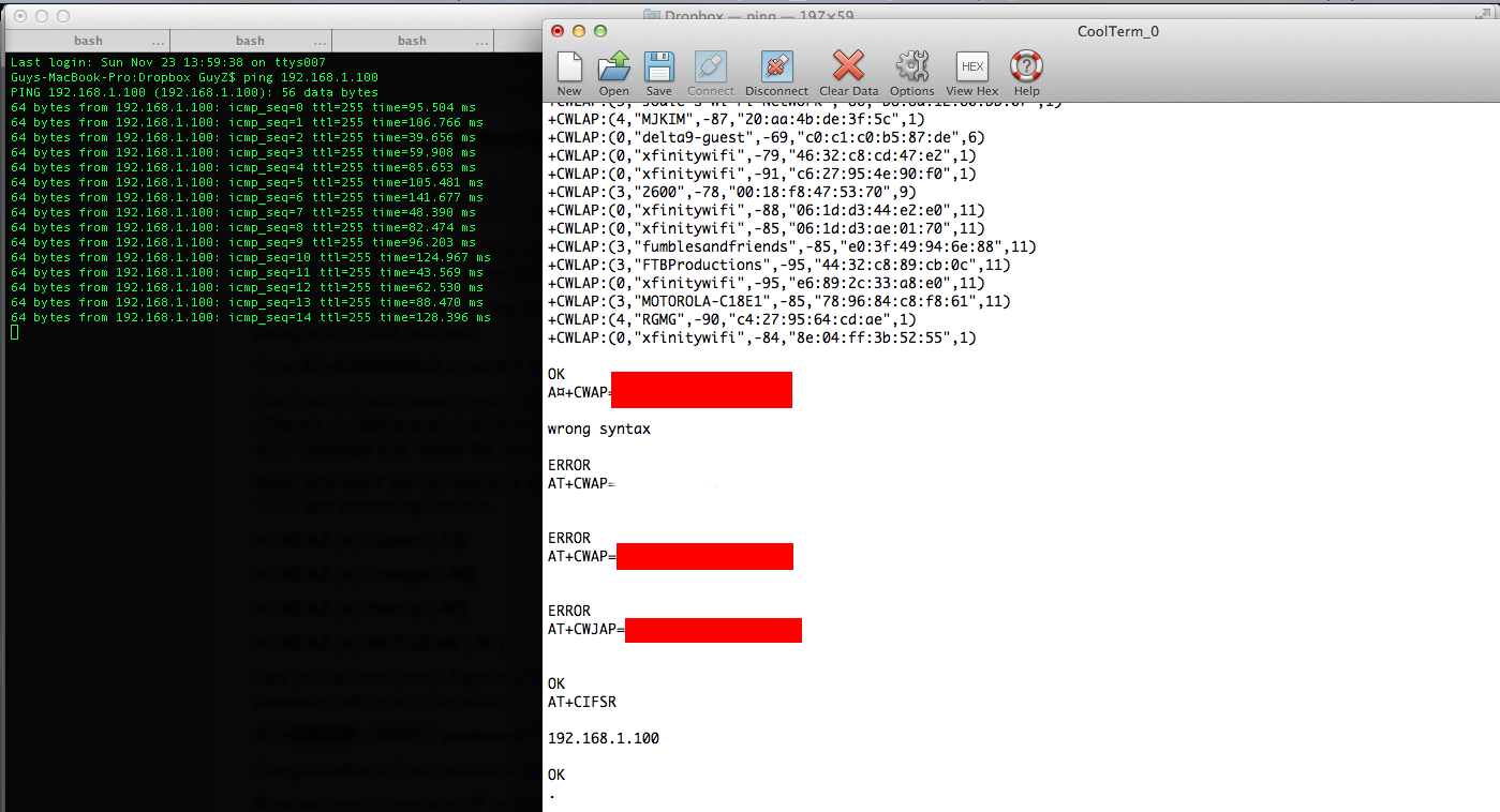
- You should see a bunch of commands going through, including a list of available APs. Eventually, you should see the IP address assigned to the module printed.
- ping the IP address obtained in (3). If that works (similar to the image below), then you got it working and can start doing cool stuff!
Webserver example:
Once you’ve successfully set up the device and confirmed that it can connect to a WiFi, you can try something more elaborate. the file esp8266server.py will go through the same flow as the test module, but it will also continue to setting up the device to accepting multiple connections:
send_cmd( "AT+CIPMUX=1" ) # multiple connection mode send_cmd( "AT+CIPSERVER=1,80" ) To run this module, issue the following command in the right directory:
Then, head to your browser and enter the following URL:
If everything works correctly, you should see the serial request being pushed through the serial interface. The python code would in turn serve a response back which will show on the browser. If you want to fiddle around with the response, look at this line in the code:
process_request("GOT IT! (" + str(datetime.datetime.now()) + ")") Troubleshooting:
If you encountered issues, check the following:
- Is the red LED on the module lit? If it isn’t, the board isn’t getting power.
- When trying to issue commands, do you see the blue LED on the module blinking? If not, check the RX/TX connections. If the LED is constantly lit, then one of the connections is wrong — probably RX/TX or one of the other pins.
- Are you seeing gibberish? You’re probably doing well, but try a different BAUD rate.
Testing the module via a microcontroller
Once you’ve got the module up and running with a direct serial connection, you can move on to plugging it into a microcontroller board. The steps are largely the same — you connect the RX/TX pins to the TX/RX pins of a microcontroller, or — if you’re using an Arduino like board — you can set up a SoftwareSerial interface and use any 2 digital pins for the communication.
As to powering up the device — while I have briefly tried and confirmed that a direct 5V supply could work, it is not recommended and your mileage may vary. There are multiple ways to regulate the voltage (e.g., http://rayshobby.net/?p=9734), or if you’re at the CBA lab — try using one of the larger 3.3V SOT223 voltage regulators, or a similar capable one.
If you’re using the Arduino IDE, you should check out these resources for some reference code:
The result should look something like this:
Делюсь опытом ESP8266 Wifi Serial Bridge
Здравствуйте, ни разу не писал тему на форум, но попробую. Началось всё с того когда мы с друзьями строили мини-карт-электромобиль. После установки руля захотелось иметь бортовую панель. Нашли в интернете интересный проект, называется Venator Цифровая приборная панель на автомобиль своими руками (Автор: FRUD) . Это цифровая приборная панель. К проводке авто подключается Arduino MEGA, а к ней ESP8266. ESP8266 соединяется с планшетом на Android по WIFI Bridge. А на планшете, в приложение визуализируется все показания в красивую графическую среду. Я сразу же, без раздумий поехал в другую часть города на автобусе покупать ESP8266. После того как я приехал домой я стал делать всё по инструкции, как на сайте автофил. Ну и меня конечно же не заработало. Это была прошивка fullflash_tcp2uart.bin. Затем я попробовал прошивку ESP-LINK. Тоже Wi-fi bridge не заработал. Читал разные темы на этом форуме, но к решению так и не пришёл. Судя по всему, не у меня одного такая проблема, но решения нет, но я ЕГО НАШЁЛ в 2:37 ночи). Пока я не наткнулся на одну прошивку написанную в ESPLorer. Вот как её установить и запустить Wifi Serial Bridge:
1. Установите программу NodeMCU flasher ( nodemcu/nodemcu-flasher )
2. Подключить питание к NodeMCU ESP8266 и перевести в FLASH режим (в NodeMCU надо сначала удержать кнопку FLASH, не отпуская нажать RESET, отпустить FLASH)
3. Открыть программу NodeMCU flasher выбрать порт и нажать Flash
4. После того как процесс прошивки завершён отключите и опять подайте питание на ESP8266.
5. Установите программу ESPlorer ( https://esp8266.ru/esplorer/ )
6. Запустите, в правом окне выберите ком порт, скорость (обычно 9600), нажмите кнопки RTS, DTR
7. Нажмите в программе File > Open from disk (выберите файл: https://www.roboremo.com/uploads/2/4/5/7/24571986/esp8266-tcp-to-serial-lua-code.zip (init.lua))
8. Откорректируйте под себя. Я же указал под себя:
cfg.ssid=»ECODI» //Имя сети которую будет раздавать ESP
cfg.pwd=»qwerty123″ //Пароль
cfg.ip=»192.168.4.1″ //IP-Адресс к которому будет поключение Wifi Serial Bridge
cfg.netmask=»255.255.255.0″
cfg.gateway=»192.168.4.1″ //IP-Адресс к которому будет поключение Wifi Serial Bridge
Далее можете подключить к ESP ардуино например (важно помнить что на ардуине TX к RX ESP,НА ардуине RX к TX ESP
Подключиться к раздаваемой сети «у меня ECODI»
И через Putty перейти на Raw > 192.168.4.1:3333
И получите Wifi Serial.
Суда по грамматическим ошибкам в этой статье, кажется, что её написал безграмотный 6-классник, ВПРОЧЕМ, ТАК И ЕСТЬ ^_^ =).
На этом форуме особо не часто появляюсь, так что если будут вопросы пишите vk.com/DenchaIT
WiFi-UART Serial Bridge Using ESP8266 or ESP32

One of the most well-known (appeared on Hackaday’s blog) and well-designed projects to make ESP8266 as a WiFi-UART bridge is jeelabs’s esp-link. Actually, this project is far beyond being a simple serial bridge as it also manages MQTT client pub/sub and REST HTTP requests in order to connect the MCU to the internet. Moreover, it can be used to flash the attached MCU. Esp-link has a very handy web interface stored inside the ESP. To make the test, we will use ESP8266 development board, specifically NodeMCU.
Prepare The Software
First, we need to download one of the release images of the project from releases page. The compressed file (A .tgz file is beside the download word in bold) should have 5 bin files :blank.bin, boot_v1.x.bin, esp_init_data_default.bin, user1.bin and user2.bin. The ESP8266 board should be connect after downloading one of the available download tools like: Flash download tool from Espressif or Nodemcu flasher. Now, follow the flashing guidelines available in Readme file according to your ESP8266 edition and set the bin files addresses according to your module memory size.  You can simply make the Flash download tool from Espressif find it for you by connecting it and pressing “start” to get the required specification from the boot message.
  Alternatively, you can read the boot message using a serial console with 76600 baud.
  After flashing the image files successfully, you should see a new WiFi network.
  Connect to it and type this IP address into the browser http://192.168.4.1 . Now, you should see the home page.
Prepare The Hardware
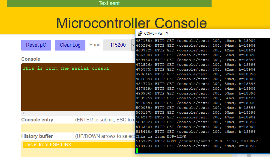
To test the serial bridge code, we will achieve the following connection: TX0 from ESP with RX of the device and RX0 with TX of the device that sends serial information and needed to be bridged via WiFi. For the sake of the test, the device here would be a USB-TTL cable (USB-UART converter) and the data will be sent and received from a console (PUTTY for instance).  Image Courtesy of ElecFreaks Now, let’s see some serial data fly over the air!
 Finally, I think a considered amount of time is needed to explore the other options of this amazing project!
Serial Bridge Using ESP8266 (Simpler)
The previous project could be too complicated to do the simple job of converting Serial connection to a WiFi connection. So I decided to port a project described in the rest of this article written in Arduino. The ported code works on ESP8266 and can be download from here: