How to interface ESP8266 with STM32
Learn how to interface the ESP8266 WiFi module with the STM32 microcontroller by reading our guide. Discover the steps involved in connecting the two devices, and access an example code to help you get started.
Disclaimer : Electricity is always dangerous. Proper skill is required to work with electricity. Do work at your own risk. The author will not be responsible for any misuse or harmful act or any mistake you make. The contents of this website are unique and copyright protected. Kindly don’t do any nonsensical act of copying and claiming it as yours. Most of the articles published here are kept open-source to help you. Take the knowledge for free and use it, but if you are interested you can buy the ready resources offered here. If you need any help or guidance feel free to comment below, the author will try to help you. Also, there can be affiliation links in the article. Which will not affect you anyway, but allows the author with some commission. So please don’t take it otherwise. Thanks.
About STM32:
STM32 is a family of microcontrollers that are widely used in embedded systems, offering a range of powerful features such as low power consumption, high performance, and a rich set of peripherals. One of the most useful peripherals in STM32 microcontrollers is the WiFi module, which provides wireless communication capabilities to a device. In this article, we will discuss STM32 WiFi communication and how it can be used to build wireless applications.

About WiFi modules:
WiFi communication is a wireless communication technology that uses radio waves to transmit and receive data over a local area network (LAN). It is a widely used technology for wireless communication and is supported by most modern electronic devices. WiFi communication is based on the IEEE 802.11 standard, which defines the physical and data link layers of the protocol.

Among these, the ESP8266 is the most popular which is also known as ESP-01.
Interfacing ESP8266 with STM32:
The ESP8266 is a popular WiFi module that can be easily integrated with an STM32 microcontroller to add wireless connectivity to your embedded system. Here are the steps to interface the ESP8266 with an STM32 microcontroller:
- Hardware connections: The first step is to connect the ESP8266 module to the STM32 microcontroller. The ESP8266 module can be connected to the STM32 microcontroller through a serial interface, such as UART or SPI. The specific pins used for the serial interface will depend on the STM32 microcontroller board you are using, so be sure to consult the board’s datasheet for details.
- Software setup: Once the hardware connections are in place, you will need to set up the software to interface with the ESP8266 module. You can use the STM32 software development kit (SDK) to configure and control the ESP8266 module. The SDK provides a range of functions for configuring the ESP8266 module, such as setting the wireless protocol, configuring the wireless network, and sending and receiving data over the network.
- Initialize the ESP8266 module: Before using the ESP8266 module, you will need to initialize it by sending it some basic commands. You can do this by sending AT commands over the serial interface to the ESP8266 module. These commands will configure the module to work with your wireless network and establish a connection to the internet.
- Send and receive data: Once the ESP8266 module is initialized, you can start sending and receiving data over the wireless network. You can use the SDK to send and receive data packets over the network, and the ESP8266 module will handle the wireless communication.
- Debugging: If you encounter any issues with the ESP8266 module, you can use the debug output from the module to troubleshoot the issue. The ESP8266 module provides debug output over the serial interface, which can be viewed using a terminal emulator or similar tool.

In summary, interfacing the ESP8266 with an STM32 microcontroller is a relatively simple process that can be accomplished with just a few hardware connections and some software setup. By adding wireless connectivity to your embedded system, you can build a range of wireless applications that can be deployed in a wide range of industries and applications.
Example code:
Here’s an example code on how to interface ESP8266 with STM32 using the STM32 HAL (Hardware Abstraction Layer) library:
#include "stm32f4xx_hal.h" #include UART_HandleTypeDef huart2; void SystemClock_Config(void); static void MX_GPIO_Init(void); static void MX_USART2_UART_Init(void); void ESP8266_Init(void) < char buffer[50]; HAL_UART_Transmit(&huart2, (uint8_t*)"AT+RST\r\n", strlen("AT+RST\r\n"), 1000); HAL_Delay(2000); HAL_UART_Transmit(&huart2, (uint8_t*)"AT+CWMODE=1\r\n", strlen("AT+CWMODE=1\r\n"), 1000); HAL_Delay(2000); sprintf(buffer, "AT+CWJAP=\"SSID\",\"password\"\r\n"); HAL_UART_Transmit(&huart2, (uint8_t*)buffer, strlen(buffer), 1000); HAL_Delay(2000); >void ESP8266_SendData(char* data) < char buffer[50]; sprintf(buffer, "AT+CIPSEND=%d\r\n", strlen(data)); HAL_UART_Transmit(&huart2, (uint8_t*)buffer, strlen(buffer), 1000); HAL_Delay(1000); HAL_UART_Transmit(&huart2, (uint8_t*)data, strlen(data), 1000); HAL_Delay(1000); >int main(void) < HAL_Init(); SystemClock_Config(); MX_GPIO_Init(); MX_USART2_UART_Init(); ESP8266_Init(); while (1) < ESP8266_SendData("Hello World!"); HAL_Delay(5000); >> void SystemClock_Config(void) < RCC_OscInitTypeDef RCC_OscInitStruct = ; RCC_ClkInitTypeDef RCC_ClkInitStruct = ; RCC_PeriphCLKInitTypeDef PeriphClkInit = ; /** Configure the main internal regulator output voltage */ __HAL_RCC_PWR_CLK_ENABLE(); __HAL_PWR_VOLTAGESCALING_CONFIG(PWR_REGULATOR_VOLTAGE_SCALE1); /** Initializes the CPU, AHB and APB busses clocks */ RCC_OscInitStruct.OscillatorType = RCC_OSCILLATORTYPE_HSI; RCC_OscInitStruct.HSIState = RCC_HSI_ON; RCC_OscInitStruct.HSICalibrationValue = RCC_HSICALIBRATION_DEFAULT; RCC_OscInitStruct.PLL.PLLState = RCC_PLL_NONE; if (HAL_RCC_OscConfig(&RCC_OscInitStruct) != HAL_OK) < Error_Handler(); >/** Initializes the CPU, AHB and APB busses clocks */ RCC_ClkInitStruct.ClockType = RCC_CLOCKTYPE_HCLK|RCC_CLOCKTYPE_SYSCLK |RCC_CLOCKTYPE_PCLK1|RCC_CLOCKTYPE_PCLK2; RCC_ClkInitStruct.SYSCLKSource = RCC_SYSCLKSOURCE_HSI; RCC_ClkInitStruct.AHBCLKDivider = RCC_SYSCLK_DIV1; RCC_ClkInitStruct.APB1CLKDivider = RCC_HCLK_DIV1; RCC_ClkInitStruct.APB2CLKDivider = RCC_HCLK_DIV1; if (HAL_RCC_ClockConfig(&RCC_ClkInitStruct, FLASH_LATENCY_0) != HAL_OK) < Error_Handler(); >PeriphClkInit.PeriphClockSelection = RCC_PERIPHCLK_USART2; PeriphClkInit.Usart2ClockSelection = RCC_USART2CLKSOURCE_PCLK1; if (HAL_RCCEx_PeriphCLKConfig &PeriphClkInit) != HAL_OK) < Error_Handler(); >> static void MX_USART2_UART_Init(void) < huart2.Instance = USART2; huart2.Init.BaudRate = 115200; huart2.Init.WordLength = UART_WORDLENGTH_8B; huart2.Init.StopBits = UART_STOPBITS_1; huart2.Init.Parity = UART_PARITY_NONE; huart2.Init.Mode = UART_MODE_TX_RX; huart2.Init.HwFlowCtl = UART_HWCONTROL_NONE; huart2.Init.OverSampling = UART_OVERSAMPLING_16; if (HAL_UART_Init(&huart2) != HAL_OK) < Error_Handler(); >> static void MX_GPIO_Init(void) < GPIO_InitTypeDef GPIO_InitStruct = ; /* GPIO Ports Clock Enable */ __HAL_RCC_GPIOA_CLK_ENABLE(); /*Configure GPIO pin : PA0 */ GPIO_InitStruct.Pin = GPIO_PIN_0; GPIO_InitStruct.Mode = GPIO_MODE_INPUT; GPIO_InitStruct.Pull = GPIO_NOPULL; HAL_GPIO_Init(GPIOA, &GPIO_InitStruct); > void Error_Handler(void) < __disable_irq(); while (1) < >> #ifdef USE_FULL_ASSERT void assert_failed(uint8_t file, uint32_t line) < >#endif / USE_FULL_ASSERT */ In this example, we have implemented two functions for interfacing with the ESP8266 module: ESP8266_Init() and ESP8266_SendData() . The ESP8266_Init() function initializes the ESP8266 module by resetting it, setting it to Station mode, and connecting it to a WiFi network. The ESP8266_SendData() the function sends a string of data to the module.
The main function initializes the system clock, GPIO pins, and UART for communication. It then calls the ESP8266_Init() function to initialize the module, and sends the string “Hello World!” to the module every 5 seconds using the ESP8266_SendData() function.
Note: Note that this is just an example code and it might require modifications to work properly with your specific setup and requirements.
To use this code, you will need to make sure that you have connected the ESP8266 module to the STM32 microcontroller correctly. The ESP8266 module should be connected to the UART interface of the STM32, with the TX pin of the module connected to the RX pin of the STM32, and the RX pin of the module connected to the TX pin of the STM32.
You will also need to modify the code to match the SSID and password of the WiFi network you want to connect to. You can do this by modifying the ssid and password variables in the ESP8266_Init() function.
Once you have made the necessary modifications to the code, you can compile and upload it to your STM32 microcontroller using your preferred IDE or toolchain.
Conclusion:
In conclusion, interfacing the ESP8266 module with the STM32 microcontroller can enable you to add WiFi connectivity to your projects. With the example code provided, you can get started with implementing this interface in your own projects.
Read more on:
For Professional Designs or Help:
Создание веб-сервера на основе ESP8266 и платы STM32F103C8
Сфера интернета вещей (Internet of Things, IoT) является одной из активно развивающихся в современном мире. В этой сфере важную роль играют модули ESP8266, которые отличаются широким набором функциональных возможностей при относительно низкой цене. Ранее на нашем сайте мы уже рассматривали следующие проекты тематики интернета вещей на основе модуля ESP8266:
В этой же статье мы рассмотрим подключение модуля ESP8266 к плате STM32F103C8 и осуществим выход в сеть в интернет. Также мы будем передавать данные на веб-страницу, расположенную на веб-сервере, организованном на основе модуле ESP8266.
Необходимые компоненты
- Модуль ESP8266 (купить на AliExpress).
- Blue Pill STM32F103C8 board (отладочная плата STM32, «синяя таблетка») (купить на AliExpress).
- Ноутбук и точка доступа Wi-Fi.
Общие принципы работы модуля ESP8266
Большинство людей называют ESP8266 модулем Wi-Fi, но на самом деле это микроконтроллер. ESP8266 — это название микроконтроллера, разработанного компанией Espressif Systems, базирующейся в Шанхае. Данный микроконтроллер имеет возможность работы с технологией Wi-Fi, поэтому он широко используется в качестве модуля Wi-Fi. Существует множество типов модулей ESP8266, доступных в диапазоне от ESP8266-01 до ESP8266-12. В данной статье мы будем использовать модуль ESP8266-01. Однако все модули ESP имеют только один тип процессора ESP и отличаются только типом используемого интерфейсного модуля. Интерфейсный модуль микроконтроллера ESP8266-01 имеет только 2 вывода GPIO, а другие модули ESP могут иметь большее количество выводов.
Модуль ESP8266 имеет 8 контактов. Его внешний вид и распиновка показаны на следующих рисунках.


Назначение контактов модуля ESP8266:
- 1 – земля, 8 – питание. По документации напряжение подается до 3,6 В – это важно учесть при работе с Ардуино, на которую обычно подают 5 В.
- 6 – RST, нужна для перезагрузки микроконтроллера при подаче на него низкого логического уровня.
- 4 – CP_PD, также используется для перевода устройства в энергосберегающий режим.
- 7 и 0 – RXD0 и TXD0, это аппаратный UART (последовательный порт), необходимый для перепрошивки модуля.
- 2 – TXD0, к этому контакту подключается светодиод, который загорается при низком логическом уровне на GPIO1 и при передаче данных по UART.
- 5 – GPIO0, порт ввода и вывода, также позволяет перевести устройство в режим программирования (при подключении порта к низкому логическому уровню и подачи напряжения).
- 3 – GPIO2, порт ввода и вывода.
К сожалению, модуль ESP8266 не является «дружественным» к макетной плате (breadboard friendly) и поэтому его нельзя на ней непосредственно закрепить.
Для управления работой модуля ESP8266 могут использоваться AT команды. Список AT команд, наиболее часто используемых при работе с модулем ESP8266, приведен в следующей таблице.

Полный же список AT команд, применимых для работы с модулем ESP8266, можно посмотреть по этой ссылке.
Схема проекта
Схема подключения модуля ESP8266 к плате STM32F103C8 представлена на следующем рисунке.
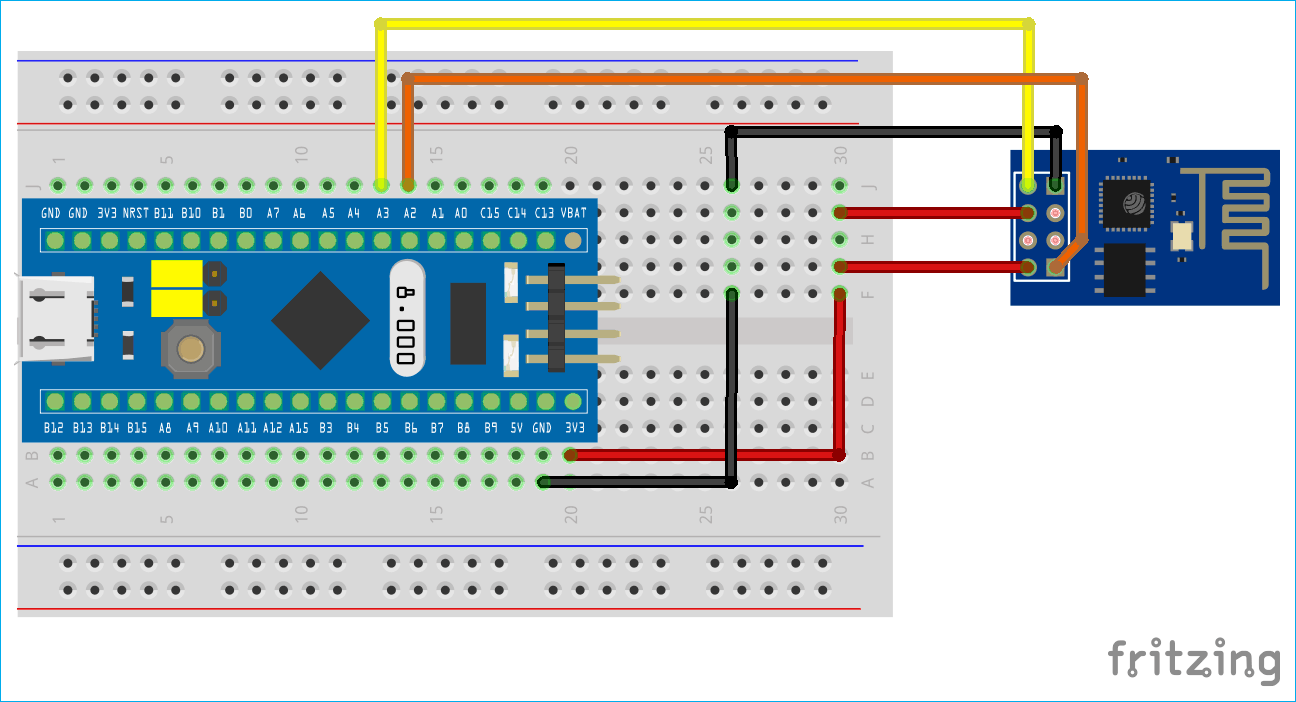
Схема соединений между модулем ESP8266 и платой STM32F103C8 представлена в следующей таблице.
| ESP8266 | STM32F103C8 |
| VCC | 3.3V |
| GND | G |
| CH_PD | 3.3V |
| TX | PA3 |
| RX | PA2 |
Плата SMT32F103C8 имеет три набора портов последовательной связи (UART), их местоположение и рабочее напряжение показаны в следующей таблице.
| Последовательный порт | Контакты | Рабочее напряжение |
| Serial1 (TX1,RX1) | PA9, PA10, PB6,PB7 | 5V |
| Serial2 (TX2,RX2) | PA2, PA3 | 3.3V |
| Serial3 (TX3,RX3) | PB10, PB11 | 5V |
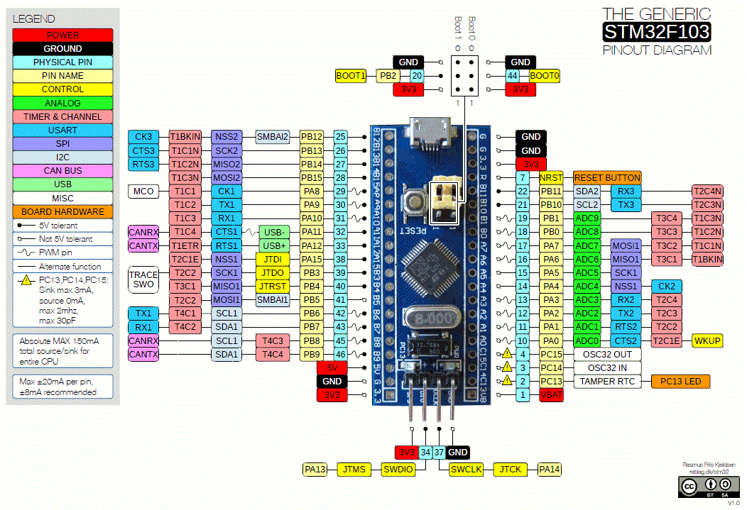
Полная распиновка платы SMT32F103C8 представлена на следующем рисунке.
Для взаимодействия между модулем ESP8266 и платой STM32F103C8 используется последовательная связь. С этой целью контакты TX & RX модуля ESP8266 подключены ко второму последовательному порту (serial2 port, контакты PA2 & PA3) платы STM32.
Объяснение программы для платы STM32
Полный код программы приведен в конце статьи, здесь же мы кратко рассмотрим его основные фрагменты.
Мы будем использовать среду Arduino IDE для написания программы и ее загрузки в плату STM32.
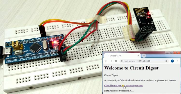
После загрузки кода программы в плату откройте в Arduino IDE монитор последовательного порта связи (Tools>>Serial Monitor). В этом окне вы увидите IP адрес, скопируйте его и вставьте его в строку браузера, в результате этого вы увидите в браузере сформированную модулем ESP8266 веб-страницу. Помните, что ваш компьютер и модуль ESP8266 при этом должны быть подключены к одной и той же Wi-Fi сети.
Первым делом в программе мы инициализируем последовательную связь с монитором последовательного порта и последовательную связь с модулем ESP8266.