- Saved searches
- Use saved searches to filter your results more quickly
- License
- NaoNaoMe/ESP8266-WiFi-UART-transparent-bridge
- Name already in use
- Sign In Required
- Launching GitHub Desktop
- Launching GitHub Desktop
- Launching Xcode
- Launching Visual Studio Code
- Latest commit
- Git stats
- Files
- README.md
- About
- WiFi-UART Serial Bridge Using ESP8266 or ESP32
- Prepare The Software
- Prepare The Hardware
- Serial Bridge Using ESP8266 (Simpler)
- ESP8266 UART WIFI Shield use guide
- 3 Comments
Saved searches
Use saved searches to filter your results more quickly
You signed in with another tab or window. Reload to refresh your session. You signed out in another tab or window. Reload to refresh your session. You switched accounts on another tab or window. Reload to refresh your session.
Transparent serial communication sketch in Arduino IDE
License
NaoNaoMe/ESP8266-WiFi-UART-transparent-bridge
This commit does not belong to any branch on this repository, and may belong to a fork outside of the repository.
Name already in use
A tag already exists with the provided branch name. Many Git commands accept both tag and branch names, so creating this branch may cause unexpected behavior. Are you sure you want to create this branch?
Sign In Required
Please sign in to use Codespaces.
Launching GitHub Desktop
If nothing happens, download GitHub Desktop and try again.
Launching GitHub Desktop
If nothing happens, download GitHub Desktop and try again.
Launching Xcode
If nothing happens, download Xcode and try again.
Launching Visual Studio Code
Your codespace will open once ready.
There was a problem preparing your codespace, please try again.
Latest commit
Git stats
Files
Failed to load latest commit information.
README.md
Transparent serial communication sketch in Arduino IDE.
Is anyone interested in serial communication over the internet?
ESP8266-Azure-IoT-Hub-UART-transparent-bridge might be a good example.
This sketch used with RM Classic.
You could find a tutorial on my youtube channel.
People who visit this repository might be interested in the UartWiFiBoard.
The UartWiFiBoard is battery-powered stand-alone uart-wifi board so that the board can establish connection wifi network by itself.
You can communicate uart data over wifi, when you connect to the board’s ip address by terminal apps.
When you send messages to the board’s ip address, the board transmit uart data to your target and vice-versa.

About
Transparent serial communication sketch in Arduino IDE
WiFi-UART Serial Bridge Using ESP8266 or ESP32

One of the most well-known (appeared on Hackaday’s blog) and well-designed projects to make ESP8266 as a WiFi-UART bridge is jeelabs’s esp-link. Actually, this project is far beyond being a simple serial bridge as it also manages MQTT client pub/sub and REST HTTP requests in order to connect the MCU to the internet. Moreover, it can be used to flash the attached MCU. Esp-link has a very handy web interface stored inside the ESP. To make the test, we will use ESP8266 development board, specifically NodeMCU.
Prepare The Software
First, we need to download one of the release images of the project from releases page. The compressed file (A .tgz file is beside the download word in bold) should have 5 bin files :blank.bin, boot_v1.x.bin, esp_init_data_default.bin, user1.bin and user2.bin. The ESP8266 board should be connect after downloading one of the available download tools like: Flash download tool from Espressif or Nodemcu flasher. Now, follow the flashing guidelines available in Readme file according to your ESP8266 edition and set the bin files addresses according to your module memory size.  You can simply make the Flash download tool from Espressif find it for you by connecting it and pressing “start” to get the required specification from the boot message.
  Alternatively, you can read the boot message using a serial console with 76600 baud.
  After flashing the image files successfully, you should see a new WiFi network.
  Connect to it and type this IP address into the browser http://192.168.4.1 . Now, you should see the home page.
Prepare The Hardware
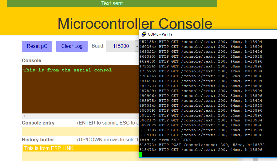
To test the serial bridge code, we will achieve the following connection: TX0 from ESP with RX of the device and RX0 with TX of the device that sends serial information and needed to be bridged via WiFi. For the sake of the test, the device here would be a USB-TTL cable (USB-UART converter) and the data will be sent and received from a console (PUTTY for instance).  Image Courtesy of ElecFreaks Now, let’s see some serial data fly over the air!
 Finally, I think a considered amount of time is needed to explore the other options of this amazing project!
Serial Bridge Using ESP8266 (Simpler)
The previous project could be too complicated to do the simple job of converting Serial connection to a WiFi connection. So I decided to port a project described in the rest of this article written in Arduino. The ported code works on ESP8266 and can be download from here:
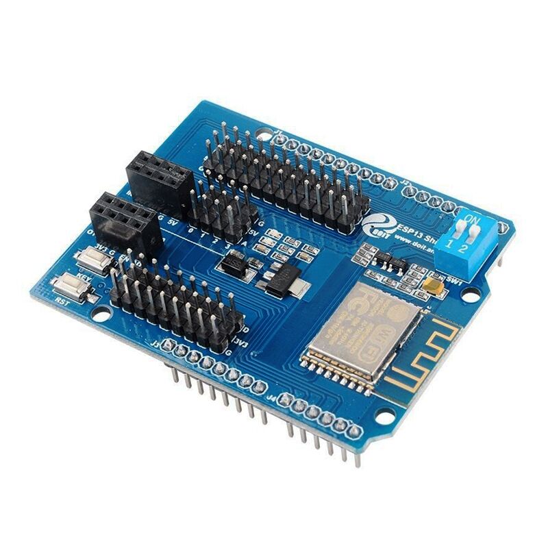
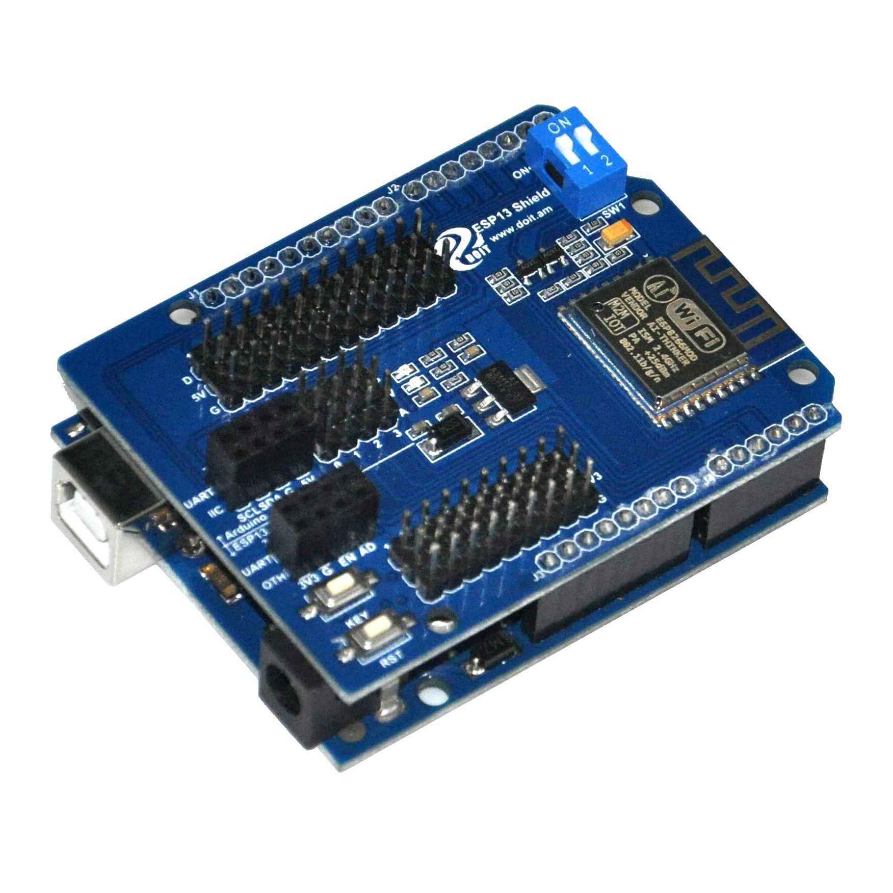
ESP8266 UART WIFI Shield use guide
- Wifi protocol 802.11 b/g/n ;
- STA/AP work mode;
- integrated TCP/IP stack, support one socket;
- work as TCP/UDP Serve or Client mode;
- serial portbaud rate: 1200/2400/4800/9600/19200/38400/57600/74800/ 115200 bps;
- serial port width:5/6/7/8 bits;;
- Extended Arduino Pin D2/3/4/5/6/7/8/9/10/11/12/13;
- Extended ESP8266 GPIO Pin 0/2/4/5/9/10/12/13/14/15/16/ADC/EN/UART TX/UART RX;
- RESET;
- KEY reset;
- WiFi current:working:≈70mA(200mA MAX),sleep: Wifi or Serial port get data
flash every half second————————————->the module is in configuration mode
flash every second—————————————–>wifi module works in STA mode trying to connect wifi router
Steady on———————————————–> enter into AP or STA mode
Quick start:
Example A: Enter configuration mode
The wifi module factory default is in configuration mode. You should complete configuration and then start transmission mode. If you are working in transmission mode, you can push and hold KEY button for more than 1 second and back to configuration mode. Please take following steps to config the module
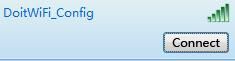
1) Turn on the power of the module and use another laptop or smart phone to connect wifi ssid “DoitWiFi_Config”。wifi password is:“12345678”(you can even use empty password to connect this ssid)
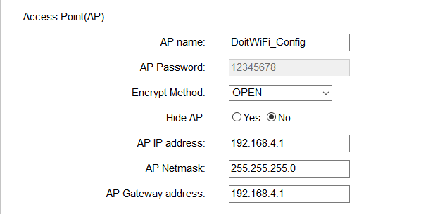
2) Open your laptop brower and access http://192.168.4.1, you will see following page:

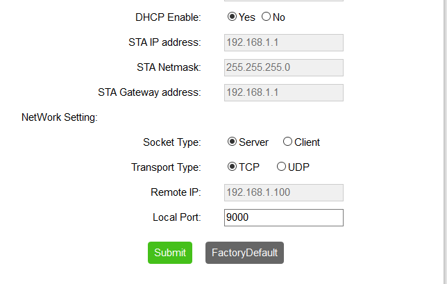
3) Do configuration as per above picture and click submit.
4) After submitting, the module will reboot and then enter into AP mode. Please set serial port parameters as 9600,n,8,1。
WiFi working mode hotspot(AP),ssid is “DoitWiFi_Config”,password: “12345678”. TCP Server listening port 9000. these configuration is Factory Default setting.
Arduino data send to WiFi through serial port :
Step 1) connect Arduino UNO to wifi module as per following picture
Step 2) set the two switch positions to OFF, this will disconnect wifi module from Arduino serial port.
Step 3) Load following code into Arduino IDE
Step 4) Set WIFI modue two switches to ON position which will connect wifi module to Arduino serial port.
Step 5) Use your laptop to search wifi hotspot ssid:“DoitWiFi_Config”,password “12345678”。
Step 6) run tcp udp testing/debug software in laptop.
We suggest you use tcp udp debugger which can be downloaded from:https://osoyoo.com/driver/TCPUDPDbg.rar
Run tcp udp debugger ,create a tcp client mode connection,DestIP :192.168.4.1,Port:9000。LocalPort:Auto。

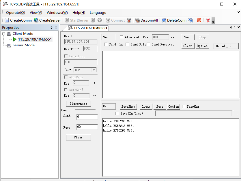
click Connect,you will see Arduino send data “hello ESP8266 WiFi” very second

Example B: Connect remote server:
we will use Doit.am WAN TCP tool to test communication between wifi module and remote server.。
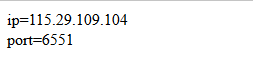
Step 1) In your laptop, type http://tcp.doit.am ,get a temperate IP and port from DOIT TCP server. In this example, suppose we get IP 115.29.109.104 port number 6551
Step 2)Push and hold KEY button in wifi mode and enter into configuration mode.
Step 3) Use your laptop to search wifi hotspot ssid:“DoitWiFi_Config”,password “12345678”
Step 4)in laptop browser, enter http://192.168.4.1
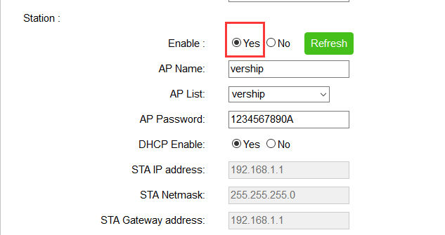
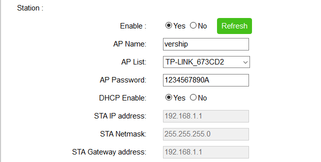
check Yes box beside Enable option.
Click refresh button, it will automatically add all local wifi in to AP list.
set AP Name and AP List to the SSID of your router (Our router ssid is vership, so we set ‘vership’ here), set AP password same as your wifi password
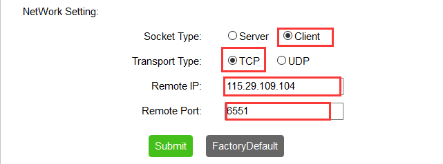
Step 5) config wifi network parameters
Remote IP: 115.28.109.104 (this IP is from step 1)
Remote Port:6551 (this port number is from step 1)
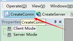
6)Run tcp udp debugger ,create a tcp client mode connection,DestIP :115.29.109.104 (from step 1),Port:6551 (from step 1)。LocalPort:Auto。
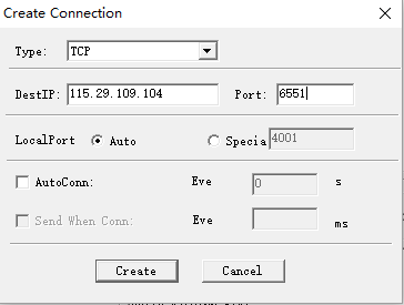
7, click Create, you will see Arduino serial data is sent to remote server every one second.
Switch between different work mode:
ESP8266 work mode relation graph:

ESP8266 wifi module serial port parameter setting options:

WiFi working mode setting
ESP8266 module wifi module can config into AP or STA working mode
If you configure the module through web page, the default mode is AP
in station section, if you check the Yes box beside Enable, the mode will change to STA. Refresh button and “AP List” drop down menu will be enabled. Click refresh , all available wifi hotspot ssid will be added into AP list
Network configuration
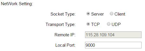
Wifi module can be configured in Server mode or client mode. WiFi module only support one Socket
When working in “Server” mode,“Remote IP” is disabled。“Local Port” fieldshould have a listening port number.
When working in client mode,“Remote IP” input field will become enabled
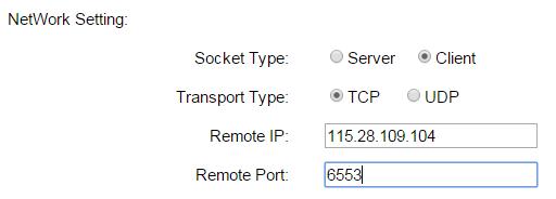
Transport type can be set to TCP or UDP。
Factory default reset
You can click “FactoryDefault” to restore factory default setting as following:
default SSID: DoitWifi_Ser2Net
default wifi password: 12345678
default web config url: http://192.168.4.1
default client mode: TCP server.
default listening port : 9000
default serial port parameter: 9600,n,8,1
3 Comments
Hi,
your examples is only esp shield-> internet but there is no example internet->esp shield.
Can you explain how to send data from a browser to arduino via this esp shield?
For example send pin=13 so arduino che recive command to light led on pin 13. I’m trying to connect in this way: http:\\192.168.4.1:9000\?pin=13 but Serial.readString() is blank.
Thank you