- Урок 15. Bluetooth модуль HC-06 подключение к Arduino. Управление устройствами с телефона.
- Bluetooth Module with Arduino (AT-09, MLT-BT05, HM-10)
- Parts List and Wiring
- CC2541 Help Menu
- NOTE: If an HM-10 module is being used, a slightly different protocol may be needed. For example, the help would be printed out as «AT+HELP?» instead of «AT+HELP» — For the module used on this site, the code above suffices.
- Configuring CC254x Parameters with Arduino Code
Урок 15. Bluetooth модуль HC-06 подключение к Arduino. Управление устройствами с телефона.
ГЛАВНАЯ / Уроки и проекты / Урок 15. Bluetooth модуль HC-06 подключение к Arduino. Управление устройствами с телефона.
Очень часто в ваших проектах возникает необходимость в дистанционном управлении или передачи данных с ваших телефонных гаджетов.
Один из самых популярных и распространенных методов обмена данными посредством Bluetooth.
Сегодня мы разберем простые примеры как можно подключить Bluetooth модуль к Arduino и настроить дистанционное управление с телефона.
Нам понадобится:
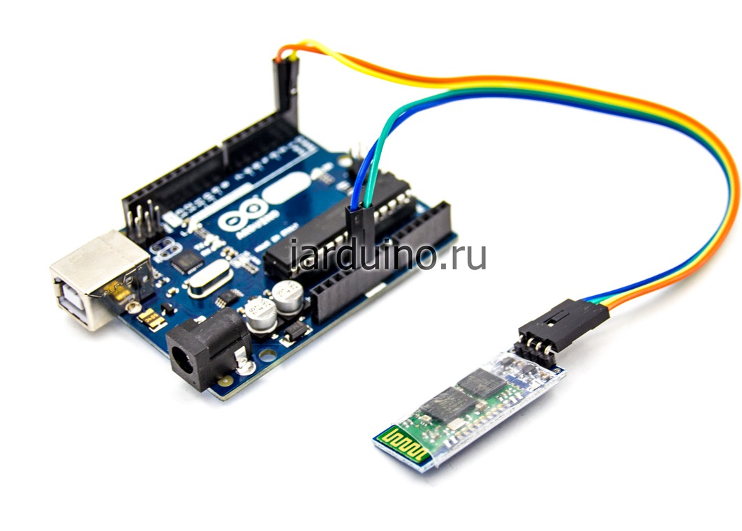
Схема подключения Bluetooth к Arduino:
Подключать Bluetooth модуль к микроконтроллеру Arduino удобнее всего с помощью проводков ПАПА-МАМА.
| Arduino | Bluetooth |
|---|---|
| Pin 1 (TX) | RXD |
| Pin 0 (RX) | TXD |
| GND | GND |
| 5V | VCC |
Будьте внимательны, подключать подключать нужно TX -> RXD ,RX -> TXD.
Теперь необходимо записать пробный код программы:
Во время загрузки скетча необходимо что бы Bluetooth модуль был отключен от микроконтроллера arduino. В противном случае скетч не запишется, потому что связь с Bluetooth модулем происходит по одному и томуже порту RX и TX, что и USB.
int val; int LED = 13; void setup() < Serial.begin(9600); pinMode(LED, OUTPUT); digitalWrite(LED, HIGH); >void loop() < if (Serial.available()) < val = Serial.read(); // При символе "1" включаем светодиод if (val == '1') < digitalWrite(LED, HIGH); >// При символе "0" выключаем светодиод if ( val == '0') < digitalWrite(LED, LOW); >> >
После того как скетч записан и Bluetooth модуль подключен к Arduino, можно перейти к следующему шагу.
Подключение Bluetooth к телефону
Желательно в качестве источника питания для arduino использовать не USB, а внешний Блок питания на 9 В.
- Включаем Bluetooth на телефоне и ищем новые устройства
- Находим в списке расстройств «HC-06″ и подключаемся к нему.
- Телефон спросит пин-код. необходимо ввести «1234» или «0000«
- Ура. Устройство подключено.
Теперь нужно скачать bluetooth terminal на ваш телефон. Мы рассмотрим на примере платформы Android.
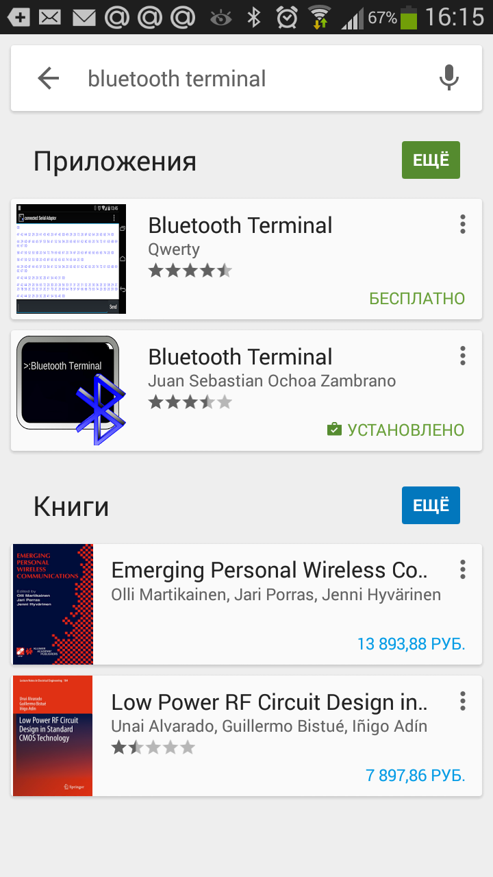
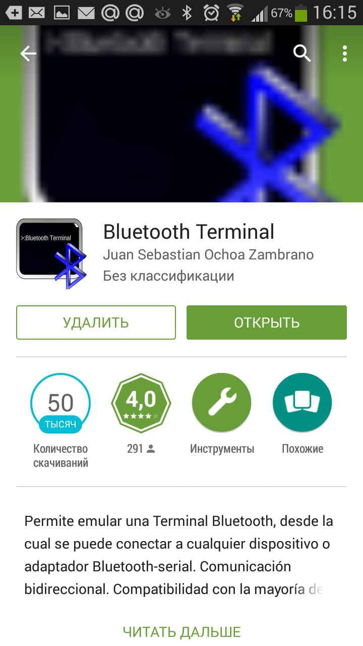
Вы можете установить разные bluetooth терминалы, как правило они отличаются только разными дизайнами, функционал от этого не меняется. Так же можно найти и терминал и для продуктов ios.
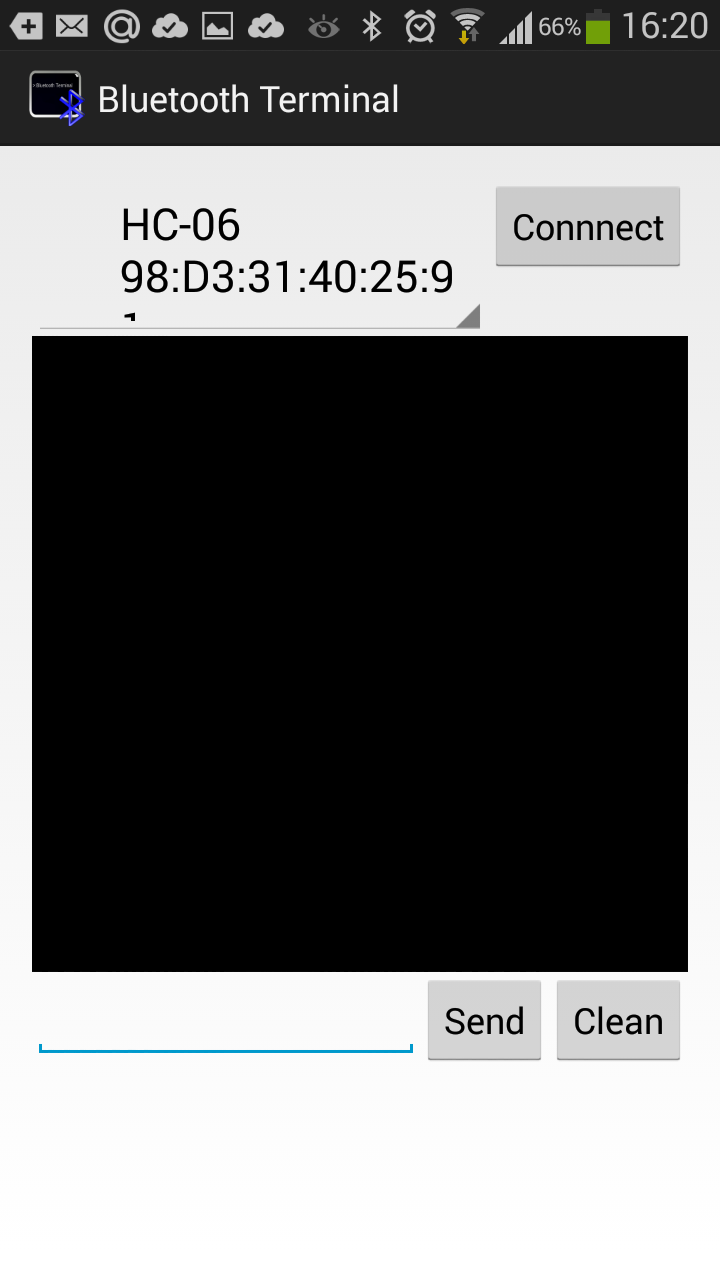
После того как мы установили терминал, запускаем его выбираем наш bluetooth модуль HC-06 и подключаемся к нему.
Пришло время попробовать проект в деле. Пишем в терминале цифру «0» и отправляем. Светодиод L который находится на плате arduino рядом с pin 13, должен погаснуть. Теперь отправим через терминал цифру «1» и светодиод L должен зажечься.
Демонстрация работы:

Домашняя работа:
- Изменить скетч так, что бы светодиод зажигался и потухал с помощью одной и той же команды например «G».
- Дописать скетч и научить его преобразовывать текстовые данные приходящие через блютус в цифровые и реализовать димер, зажигать светодиод с помощью ШИМ, на заданную яркость от 0 до 254 приходящую через bluetooth.
Bluetooth Module with Arduino (AT-09, MLT-BT05, HM-10)
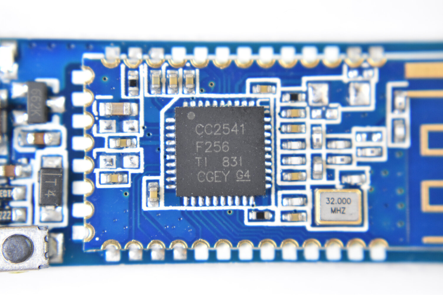
A range of devices use Texas Instruments’ CC2540/CC2541 system-on-chip as a tiny Bluetooth Low Energy (BLE) interface for integrating applications into the Internet of Things (IoT). The CC2541 is compatible with both the Android and iOS platforms, and can be used to talk between a smartphone and Arduino board (see my previous posts on this: here). In this tutorial, I will dive into the variations of CC2541 BLE board such as the AT-09, MLT-BT05, HM-10, JDY-08, etc. I will use either the specific module name or a blanketed “CC2541-based module” reference to refer to the BLE modules. The general process for interfacing with each module is nearly the same, however, some particularities define how each responds and functions depending on the given firmware.
I will be using the BLExAR app for iOS to communicate with the CC2541 modules. Any iOS or Android app that allows communication over BLE can be used to communicate back and forth, so have the app downloaded before continuing.
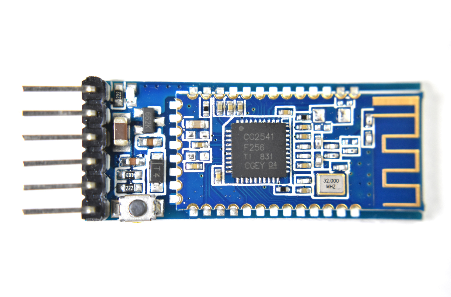
Parts List and Wiring
Only an Arduino board and a CC2541 BLE module will be needed to follow along with this tutorial. Below is a list of parts that can be purchased and where to find them, along with a few peripheral components that will be used.
- CC2541 Bluetooth Low Energy Module — $8.00 [Our Store]
- Arduino Uno Board — $11.00 [Our Store]
- Mini Breadboard — $ 3.00 [Our Store]
- Jumper Wires — $5.99 (120 pcs) [Amazon]
- 3.7V 720 mAh LiPo Battery — $11.97 (5 pcs) [Amazon]
- LEDs — $10.99 (600 pcs) [Amazon]
- Resistor Kit — $12.99 (1280 pcs) [Amazon]
- Raspberry Pi 4 Kit — $99.99 [Amazon]
The CC2541 module can communicate with an Arduino board adhering to the following wiring diagram:
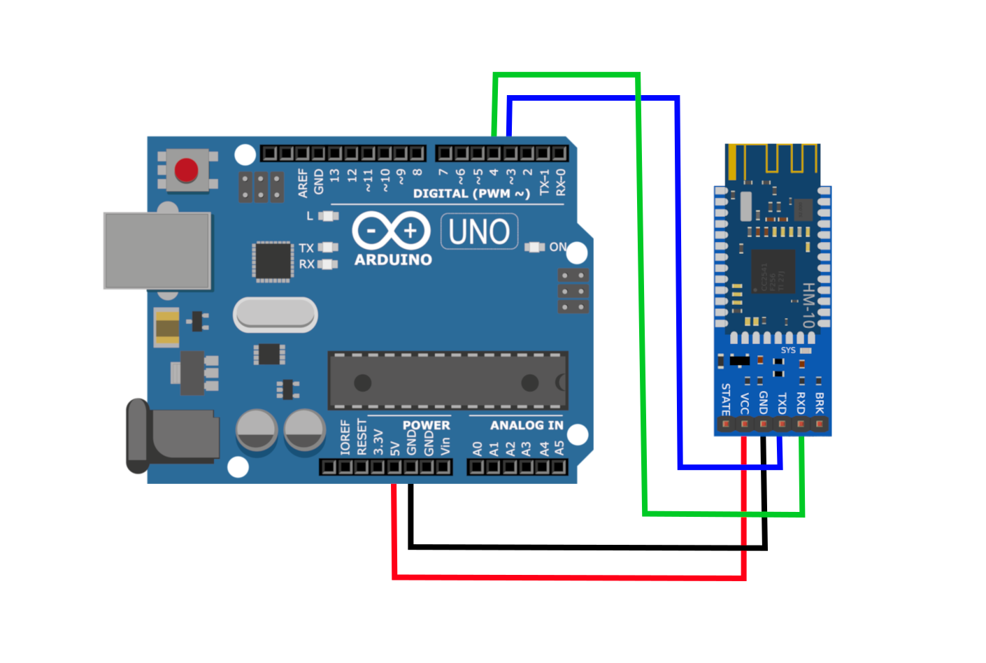
Next, we will explore the functions available to a given CC2541 BLE module to change settings such as device name, sleep state, and device characteristic ID.
CC2541 Help Menu
Several datasheets exist for the various modules based on the CC2541 Bluetooth chip. A few of them are listed below with links:
Each of the datasheets outlines the electrical characteristics and firmware breakdown for each module. Every CC254x module that is mentioned above uses the ‘AT-Command’ protocol to interface with and alter different parameters specific to each module. For example, we can change the name that is displayed on a smartphone during a BLE scan by sending the following command to the CC254x module:
To view all of the possible commands, the command “AT+HELP” should be used, which prints out the following list of possible commands and settings:

The code to replicate this particular printout, with the AT-09 or MLT-BT05, is given below.
// help menu printout for MLT-BT05 #include SoftwareSerial ble_device(3,4); String str_ii = ""; int ii_0 = 0; void setup() Serial.begin(115200); delay(1000); ble_device.begin(9600); delay(1000); // First, get all available functions from CC2541 firmware ble_help(); > void loop() > void ble_help() ble_device.println("AT+HELP"); // list all AT+ commands while (true) // loop to print all AT+ commands char in_char = ble_device.read(); if (int(in_char)==-1 or int(in_char)==42)continue;> str_ii+=in_char; if (in_char=='\n') if (str_ii==String('\r')+String('\n')) if (ii_0 == 0) ii_0 = 1; continue; > break; // break after more than 1 empty carriage return and newline > Serial.print(str_ii); str_ii = ""; > > >
NOTE: If an HM-10 module is being used, a slightly different protocol may be needed. For example, the help would be printed out as «AT+HELP?» instead of «AT+HELP» — For the module used on this site, the code above suffices.
The help menu printout is very helpful because it tells us which commands do what. If we wanted to know the Bluetooth address of our module such that we can search directly for our unique device, we can tell the BLE module to print out the device address using:
And we should see a printout similar to:
This is the 24-bit (six hex digits) address of the BLE module. In the next section, I outline the various methods for communicating with the CC254x to read and configure various parameters of the Bluetooth low energy modules.
Configuring CC254x Parameters with Arduino Code
There are a few changes that can be made with respect to the CC254x modules used here. We can change the name of the module, for example, I choose to name mine after the app being used via the AT command: “AT+NAMEBLExAR” — which was mentioned above. We can also get the Bluetooth address using the command mentioned above, “AT+LADDR” — and we can configure a range of other commands using similar protocols.
The code below carries out the following sequence of commands:
- Print all AT+ Commands
- Rename BLE module to ‘BLExAR’
- Print the BLE address
- Print the BLE UUID used for communication
- Print the firmware version of the device
- Reset the Bluetooth module to enact any changes
It is important that the BLE module is NOT connected yet. The AT+ commands can only be carried out if there is no connection yet.
// Arduino code to read and change CC254x parameters #include SoftwareSerial ble_device(3,4); String str_ii = ""; int ii_0 = 0; void setup() Serial.begin(115200); ble_device.begin(9600); delay(100); ble_help(); // uncomment to print commands delay(100); // Enter AT+ commands of interest here (BLE Address, UUIDs, Power settings) ble_cmd("AT+NAMEBLExAR","Device Name: "); // printout device name ble_cmd("AT+LADDR","Address: "); // printout BLE address ble_cmd("AT+CHAR","Char UUID: "); // printout character UUID ble_cmd("AT+VERSION","Version: "); // module version ble_cmd("AT+RESET",""); // reset BLE module > void loop() > String ble_cmd(String cmd_str,String desc_str) str_ii = ""; unsigned long t1 = millis(); ble_device.println(cmd_str); while (true) char in_char = ble_device.read(); if (int(in_char)==-1 or int(in_char)==42) if ((millis()-t1)>2000) // 2 second timeout return "Err"; > continue; > if (in_char=='\n') Serial.print("Bluetooth "+desc_str); Serial.println(str_ii.substring(0,str_ii.length())); return str_ii; > str_ii+=in_char; > > void ble_help() ble_device.println("AT+HELP"); // list all AT+ commands while (true) // loop to print all AT+ commands char in_char = ble_device.read(); if (int(in_char)==-1 or int(in_char)==42)continue;> str_ii+=in_char; if (in_char=='\n') if (str_ii==String('\r')+String('\n')) if (ii_0 == 0) ii_0 = 1; continue; > break; // break after more than 1 empty carriage return and newline > Serial.print(str_ii); str_ii = ""; > > >
An example printout from the code above is shown below as well: