Wireless VLANs
The documentation set for this product strives to use bias-free language. For the purposes of this documentation set, bias-free is defined as language that does not imply discrimination based on age, disability, gender, racial identity, ethnic identity, sexual orientation, socioeconomic status, and intersectionality. Exceptions may be present in the documentation due to language that is hardcoded in the user interfaces of the product software, language used based on RFP documentation, or language that is used by a referenced third-party product. Learn more about how Cisco is using Inclusive Language.
Table Of Contents
Configuring Access Points in VLANs
This module describes how to configure an access point to operate with the VLANs set up on a wired LAN. This chapter includes the following sections
•Understanding VLANs
•Configuring VLANs
•VLAN Configuration Example
Understanding VLANs
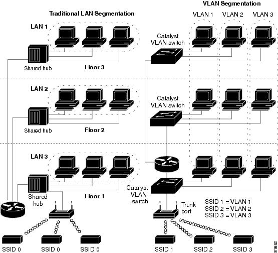
A VLAN is a switched network that is logically segmented by functions, project teams, or applications, rather than being segmented on a physical or geographical basis. For example, all workstations and servers used by a particular workgroup team can be connected to the same VLAN, regardless of their physical connections to the network or the fact that they might be intermingled with the workstations and servers of other teams. You use VLANs to reconfigure the network through software rather than by physically unplugging and moving devices or wires.
A VLAN can be thought of as a broadcast domain that exists within a defined set of switches. A VLAN consists of a number of end systems, either hosts or network equipment (such as bridges and routers), connected by a single bridging domain. The bridging domain is supported on various pieces of network equipment such as LAN switches that operate bridging protocols between them with a separate group of protocols for each VLAN.
VLANs provide the segmentation services traditionally provided by routers in LAN configurations. VLANs address scalability, security, and network management. You should consider several key issues when designing and building switched LAN networks:
•LAN segmentation
•Security
•Broadcast control
•Performance
•Network management
•Communication between VLANs
You extend VLANs into a wireless LAN by adding IEEE 802.11Q tag awareness to the access point. Frames destined for different VLANs are transmitted by the access point wirelessly on different service set indentifiers (SSIDs) with different Wired Equivalent Privacy (WEP) keys. Only the clients associated with that VLAN receive those packets. Also, packets coming from a client associated with a certain VLAN are 802.11Q tagged before they are forwarded on to the wired network.
If 802.1q is configured on the Fast Ethernet interface of an access point, the access point always sends keepalives on VLAN 1 even if VLAN 1 is not defined on the access point. As a result, the Ethernet switch connects to the access point and generates a warning message. There is no loss of function on either the access point or the switch. However, the switch log contains meaningless messages that may cause more important messages to be wrapped and not be seen.
Sending these keepalives creates a problem when all SSIDs on an access point are associated to mobility networks. If all SSIDs are associated to mobility networks, the Ethernet switch port that the access point is connected to can be configured as an access port. The access port is normally assigned to the native VLAN of the access point, which is not necessarily VLAN 1, which causes the Ethernet switch to generate warning messages saying that traffic with an 802.1q tag is sent from the access point.
You can eliminate the excessive messages on the switch by disabling the keepalive function.
Figure 1 shows the difference between traditional physical LAN segmentation and logical VLAN segmentation with wireless devices connected.
Figure 1 LAN and VLAN Segmentation with Wireless Devices
Related Documents
The following documents provide more detailed information about VLAN design and configuration:
•Cisco IOS Switching Services Configuration Guide. Click this link to browse to this document:
http://cisco.com/en/US/products/sw/iosswrel/ps5187/prod_configuration_guide09186a008017d129.html
•Cisco Internetwork Design Guide. Click this link to browse to this document:
http://www.cisco.com/en/US/docs/internetworking/design/guide/idg4.html
•Cisco Internetworking Technology Handbook. Click this link to browse to this document:
http://www.cisco.com/en/US/docs/internetworking/technology/handbook/ito_doc.html
•Cisco Internetworking Troubleshooting Guide. Click this link to browse to this document:
http://www.cisco.com/univercd/cc/td/doc/cisintwk/itg_v1/index.htm
Incorporating Wireless Devices into VLANs
The basic wireless components of a VLAN consist of an access point and a client associated to it through wireless technology. The access point is physically connected through a trunk port to the network VLAN switch on which the VLAN is configured. The physical connection to the VLAN switch is through the access point Ethernet port.
In fundamental terms, the key to configuring an access point to connect to a specific VLAN is to configure its SSID to recognize that VLAN. Because VLANs are identified by a VLAN ID, if the SSID on an access point is configured to recognize a specific VLAN ID, a connection to the VLAN is established. When this connection is made, associated wireless client devices with the same SSID can access the VLAN through the access point. The VLAN processes data to and from the clients the same way that it processes data to and from wired connections. You can configure up to 16 SSIDs on an access point, which means that you can support up to 16 VLANs. You can assign only one SSID to a VLAN.
You can use the VLAN feature to deploy wireless devices with greater efficiency and flexibility. For example, one access point can handle the specific requirements of multiple users with varied network access and permissions. Without VLAN capability, multiple access points would have to be used to serve classes of users based on their assigned access and permissions.
These are two common strategies for deploying wireless VLANs:
•Segmentation by user groups: You can segment your wireless LAN user community and enforce a different security policy for each user group. For example, you can create three wired and wireless VLANs in an enterprise environment for full-time employees, part-time employees, and guests.
•Segmentation by device types: You can segment your wireless LAN to allow different devices with different security capabilities to join the network. For example, some wireless users might have handheld devices that support only static WEP, and some wireless users might have more sophisticated devices that use dynamic WEP. You can group and isolate these devices into separate VLANs.
Configuring VLANs
Configuring a VLAN
Note When you configure VLANs on access points, the native VLAN must be VLAN 1. In a single architecture, client traffic that is received by the access point is tunneled through an IP-GRE tunnel, which is established on the access point’s Ethernet interface native VLAN. Because of the IP-GRE tunnel, some users may configure another switch port as VLAN1. This misconfiguration causes errors on the switch port.
Configuring your access point to support VLANs is a three-step process:
1. Enable the VLAN on the access point radio and Ethernet ports.
2. Assign SSIDs to VLANs.
3. Assign authentication settings to SSIDs.
This section describes how to assign SSIDs to VLANs and how to enable a VLAN on the access point radio and Ethernet ports.
For detailed instructions on assigning authentication types to SSIDs, see Authentication Types for Wireless Devices on Cisco.com, http://www.cisco.com/en/US/docs/routers/access/wireless/software/guide/SecurityAuthenticationTypes.html .
For instructions on assigning other settings to SSIDs, see Service Set Identifiers on Cisco.com, http://www.cisco.com/en/US/docs/routers/access/wireless/software/guide/ServiceSetID.html.
You can configure up to 16 SSIDs on the access point, so you can support up to 16 VLANs that are configured on your LAN. Or, the total number VLANs you can configure on your LAN is determined by the number of LANs supported by the host router.
To assign an SSID to a VLAN and enable the VLAN on the access point radio and Ethernet ports, follow these steps, beginning in privileged EXEC mode:
Tip If your network uses VLAN names, you can also assign names to the VLANs on your access point.
The following example shows how to:
•Name an SSID
•Assign the SSID to a VLAN
•Enable the VLAN on the radio and Ethernet ports as the native VLAN
Summary
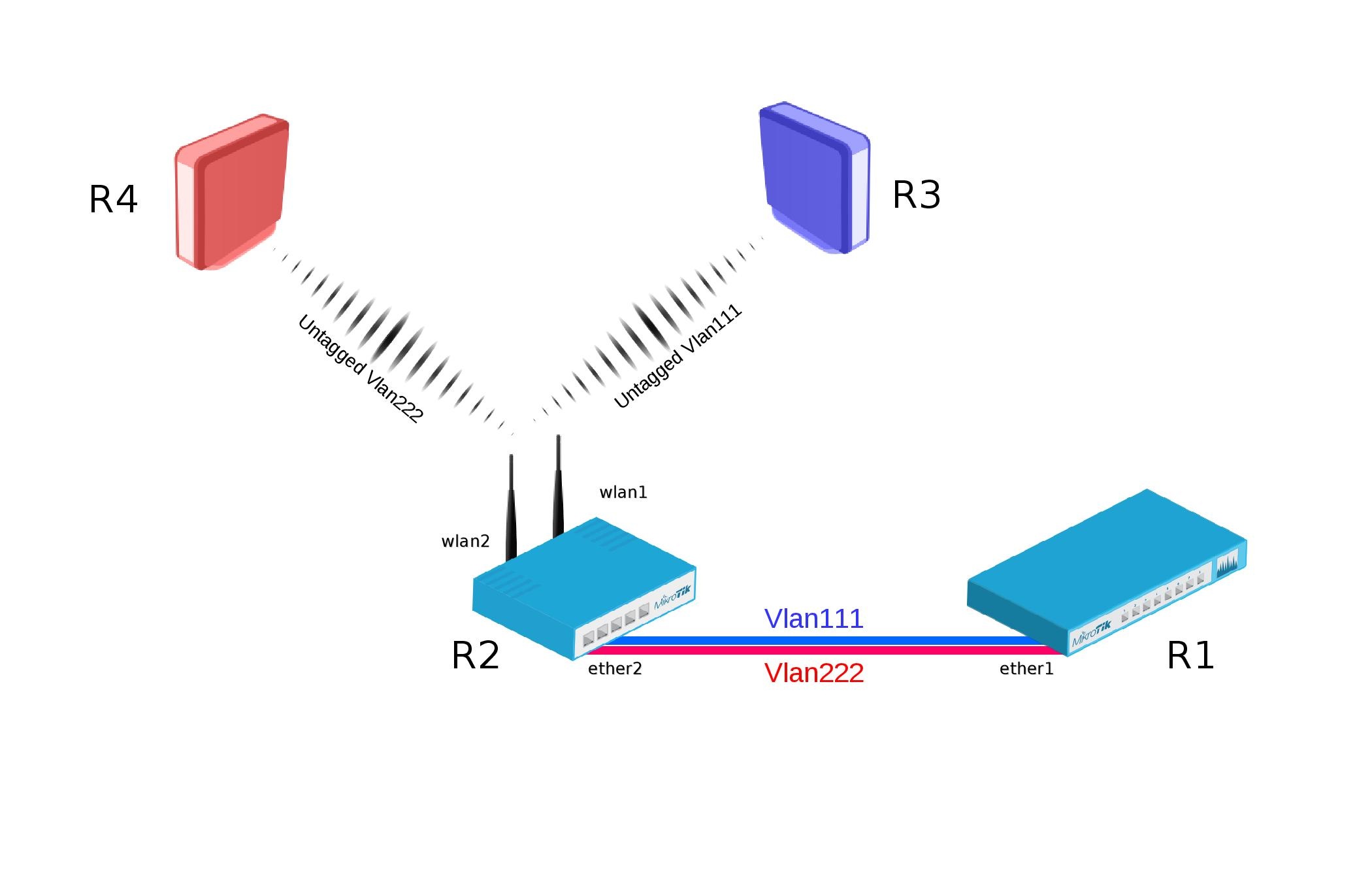
VLANs provide the possibility to isolate devices into different Layer2 segments while still using the same Layer1 medium. This is very useful in setups where you want to separate different types of devices of users. This feature is also very useful for Wireless setups since you can isolate different Virtual APs and restricting access to certain services or networks by using Firewall. Below is an example with a setup with two Access Points on the same device that isolates them into saparate VLANs. This kind of scenario is very common when you have a Guest AP and Work AP.
Example
Bridge VLAN Filtering since RouterOS v6.41 provides VLAN aware Layer2 forwarding and VLAN tag modifications within the bridge.
- Add necessary VLAN interfaces on ethernet interface to make it a VLAN trunk port. Add ip addresses on VLAN interfaces.
[admin@R1] > /interface vlan add interface=ether1 name=vlan111 vlan-id=111 add interface=ether1 name=vlan222 vlan-id=222 /ip address add address=192.168.1.1/24 interface=vlan111 add address=192.168.2.1/24 interface=vlan222
[admin@R2] > /interface wireless set [ find default-name=wlan1 ] disabled=no mode=ap-bridge security-profile=vlan111 ssid=vlan111 vlan-id=111 vlan-mode=use-tag add disabled=no master-interface=wlan1 name=wlan2 security-profile=vlan222 ssid=vlan222 vlan-id=222 vlan-mode=use-tag
- Create bridge with vlan-filtering=yes
- Add necessary bridge ports
- Add tagged interfaces under interface bridge vlan section with correct vlan-ids
[admin@R2] > /interface bridge add fast-forward=no name=bridge1 vlan-filtering=yes /interface bridge port add bridge=bridge1 interface=ether2 add bridge=bridge1 interface=wlan1 add bridge=bridge1 interface=wlan2 /interface bridge vlan add bridge=bridge1 tagged=ether2,wlan1 vlan-ids=111 add bridge=bridge1 tagged=ether2,wlan2 vlan-ids=222
Some devices have a built-in switch chip that can switch packets between Ethernet ports with wire-speed performance. Bridge VLAN filtering disables hardware offloading (except on CRS3xx series switches), which will prevent packets from being switched, this does not affect Wireless interfaces as traffic through them cannot be offloaded to the switch chip either way.
VLAN filtering is not required in this setup, but is highly recommended due to security reasons. Without VLAN filtering it is possible to forward unknown VLAN IDs in certain scenarios. Disabling VLAN filtering does have performance benefits.
- Add IP address on wlan1 interface.
- Create wireless security-profile compatible with R2 wlan1.
[admin@R3] > /ip address add address=192.168.1.3/24 interface=wlan1 /interface wireless set [ find default-name=wlan1 ] disabled=no security-profile=vlan111
- Add IP address on wlan1 interface.
- Create wireless security-profile compatible with R2 wlan2.
[admin@R4] > /ip address add address=192.168.2.4/24 interface=wlan1 /interface wireless set [ find default-name=wlan1 ] disabled=no security-profile=vlan222