- Wemos d1 wifi module
- Table of Contents
- What is LDR(light-dependent resistor)
- Components Required:
- Connection Required:
- Setting Up an broker.mqtt-dashboard.com with MQTT Client
- Programming Wemos D1 WiFi ESP8266
- Arduino Sketch
- Results:
- Wemos d1 wifi module
- Table of Contents
- Connect to WiFi
- Required Libraries
- Define Access Point SSID and Password
- Create WIFI Server and Access Point
- Wait for a connection
- Контроллер с Wi-Fi WeMos D1 на ESP8266
- С этим товаром берут
- Общие сведения
- Характеристики
- Программное обеспечение
- Комплектация
- Установка драйвера
- Ссылки
Wemos d1 wifi module
This tutorial, we will learn how connect LDR(light-dependent resistor) with Wemos D1 WiFi-ESP8266 board and posting LDR Analog data on MQTT Server. In last post, we have seen how to control LED with help of MQTT & Wemos D1 WiFi-ESP8266 board.
To execute this project, we will interface LDR (light-dependent resistor) output at Analog input Pin A0 of Wemos D1 WiFi-ESP8266 board. This project is simple concept of IOT(Internet Of Things) with the help MQTT server to get real time LDR value remotely.
Table of Contents
What is LDR(light-dependent resistor)
LDR (Light dependent Resister) or a photoresistor is a light dependent variable resistor that resistance decreases with the increase in the intensity of light. This gives an analog value so that it is connected to an analog pin of arduino board. it has an internal resistance which is very sensitive to light intensity and varies according to it. when the light will fall on the LDR sensor, its resistance will go LOW and in return the voltage across the LDR will also go LOW and as the LDR will come in dark, the resistance will go HIGH and in return the voltage will also go HIGH.
Components Required:
Connection Required:
- Connect +5V of the Arduino Wemos D1 WiFi-ESP8266 board to one pin of the LDR.
- Connect the other pin of the LDR to A0 (analog pin of the Arduino Wemos D1 WiFi-ESP8266) and one pin of the 100KΩ resistor.
- Connect the other pin of the 100KΩ resistor to GND of the Arduino Wemos D1 WiFi-ESP8266.
- Connect the 220ohm resistor to the long leg (+ve) of the LED on the breadboard.
- connect the other leg of the resistor to pin number 11 (digital pin) of the Arduino Wemos D1 WiFi-ESP8266.
- And connect shorter leg of the LED to the ground.


Setting Up an broker.mqtt-dashboard.com with MQTT Client
As we need to publish the LDR Analog value being read on Pin A0 to see remotely we need MQTT broker , “broker.mqtt-dashboard.com” is an open MQTT server , which is suitable for testing IoT devices for MQTT demo application with Arduino. The MQTT protocol provides a lightweight method of transferring information using a publish/subscribe model.
To setup and communicate with broker.mqtt-dashboard.com Broker we need install MQTT Client Android App. Follow Below steps to setup MQTT client with Android Mobile.
First, download any “MQTT client” application available in the Google Play Store / App Store and install it. In this project, an application named “MQTT client” is used, which looks like the image shown below.

Click on the “+” sign to list the additional options in the application, where we are going to add a new broker. When the button is clicked, a new screen appears as shown below.

Thereafter, the details of the broker need to be filled in the required field. First, click on the option “Enabled” shown in the Application. In this project, the broker.mqtt-dashboard.com is used, the details which are to be filled are given below:
Nick Name: Give a Name of Your Preference
Host: broker.mqtt-dashboard.com
Client ID:”LDRTEST” Give an ID of Your Preference
The above details need to be filled in their respective fields. All other fields are not necessary and can be left blank. After successful completion, click on the save button to save the Broker details.

After setting up an android application for MQTT Client let configure our Wemos D1 WiFi-ESP8266 with MQTT Broker
Programming Wemos D1 WiFi ESP8266
There are many Examples available for Wemos D1 WiFi Modules with ESP8266 Community Package you installed and to support MQTT Protocol we need to download and install PubSubClient library.
Please refer my earlier tutorial for how to install ESP8266 library on Arduino IDE for better understanding.

To access and interact with the ESP8266 over webserver you need to set WiFi network SSID and Password you wants to access on your Wemos D1 WiFi Board.
const char* ssid = "microdigisoft"; // Your Wi-Fi Name const char* password = "microdigisoft"; // Wi-Fi Password
Get and enter the “MQTT Server” name and uniqueID. Assign the MQTT as a client to ESP8266.
// MQTT Broker const char* ssid = ". ";//use your ssid const char* password = ". ";//use your password const char* mqtt_server = "broker.mqtt-dashboard.com"; WiFiClient espClient; PubSubClient client(espClient);
The complete code for Interfacing LDR with Wemos D1 WiFi-ESP8266 And MQTT server given below and also we need to install PubSubClient library to make MQTT broker functional with Arduino Programming.
Arduino Sketch
#include // Import ESP8266 Wifi library #include //Import PubSubClient library to initialize MQTT Protocol // Update these with values suitable for your network. const char* ssid = ". ";//use your ssid const char* password = ". ";//use your password const char* mqtt_server = "broker.mqtt-dashboard.com"; int ldrValue; WiFiClient espClient; PubSubClient client(espClient);// Define MQTT client unsigned long lastMsg = 0; #define MSG_BUFFER_SIZE (50) char msg[MSG_BUFFER_SIZE]; int value = 0; void setup_wifi() < delay(10); // We start by connecting to a WiFi network Serial.println(); Serial.print("Connecting to "); Serial.println(ssid); WiFi.mode(WIFI_STA); WiFi.begin(ssid, password); while (WiFi.status() != WL_CONNECTED) < delay(500); Serial.print("."); >randomSeed(micros()); Serial.println(""); Serial.println("WiFi connected"); Serial.println("IP address: "); Serial.println(WiFi.localIP()); > // Check for for Meaasege being received for deined topic topic void callback(char* topic, byte* payload, unsigned int length) < Serial.print("Message arrived ["); Serial.print(topic); Serial.print("] "); for (int i = 0; i < length; i++) < Serial.print((char)payload[i]); >Serial.println(); // Switch on the LED if an 1 was received as first character if ((char)payload[0] == '1') < digitalWrite(D2, LOW); // Turn the LED on (Note that LOW is the voltage level // but actually the LED is on; this is because // it is active low on the ESP-01) >else < digitalWrite(D2, HIGH); // Turn the LED off by making the voltage HIGH >> void reconnect() < // Loop until we're reconnected while (!client.connected()) < Serial.print(" n"); // prints a space between the numbers delay(1000); // wait 100ms for next reading Serial.print("Attempting MQTT connection. "); // Create a random client ID String clientId = "ESP8266Client-"; clientId += String(random(0xffff), HEX); // Attempt to connect if (client.connect(clientId.c_str())) < Serial.println("connected"); // Once connected, publish an announcement. client.publish("LEDTEST", buf); // . and resubscribe client.subscribe("LDRTEST"); >else < Serial.print("failed, rc="); Serial.print(client.state()); Serial.println(" try again in 5 seconds"); // Wait 5 seconds before retrying delay(5000); >> > void setup() < pinMode(D2, OUTPUT); // Initialize the BUILTIN_LED pin as an output Serial.begin(115200); setup_wifi(); client.setServer(mqtt_server, 1883); client.setCallback(callback); >void loop() < if (!client.connected()) < reconnect(); >client.loop(); ldrValue = analogRead(A0); // read analog input pin A0 Serial.print("LDRVALUE On Serial Port ="); // prints a space between the numbers Serial.print(ldrValue, DEC); // prints the value read Serial.print(" n"); // prints a space between the numbers sprintf(buf, "Published LDR Value=%d", ldrValue); client.publish("LDRTEST", buf); delay(1000); // wait 100ms for next reading > Now, simply compile the program & click the “Upload” button , to load the program into Wemos D1 WiFi Board. Once the Program is uploaded successfully you will see your board will connected with WiFi network with assigned SSID & Password being program with Arduino IDE.
Also You can monitor the response using Serial Monitor with connected com port for value being read on Analog Input A0 for LDR sensor.

After loading program on Wemos D1 WiFi-ESP8266 you need to subscribe and publish message with topic(here LDRTEST) which we have configured while programming ESP8266 board.

Once you subscribe the with Topic “LDRTEST” you will start getting LDR Analog Values on your MQTT Dashboard Android App as like you reading the values on Serial Monitor with connected com port.
Results:

Please share your feedback in below comment box for any doubts. Thanks!
Wemos d1 wifi module
In last tutorial, we have discussed some basic features of Wemos D1 Mini WiFi module featured with ESP8266. Now, let us explore some basic projects with this WiFi Module. As it is very much similar to Arduino Uno Board but additional onboard ESP8266 Embed with board making more interesting to do the interesting projects. This tutorial we will configure this Wemos D1 Mini Board as WiFi Access point(AP) / Server.
Table of Contents

The D1 Mini has an ESP8266 at its core, which means that it can do many of the things an Arduino board can do (analog input, digital input, I2C, etc.), but it can also handle WiFi communication. The WiFi communication enables the D1 Mini to act as a local server and so much more. In this example, I will demonstrate the simplest implementation of the D1 Mini as a WiFi server by communicating between a device (smartphone, tablet, desktop) and the D1 Mini by communicating on a local host webpage.
There are two ways for the WeMos D1 Mini to host a server: as a station and as an access point. Basically, an access point server doesn’t need another WiFi router – the WeMos D1 mini itself is the router. It broadcasts a WiFi connection and the user connects to it through SSID and password.
Let us now cover some points to configure ESP8266 module, we need to connect Wemos D1 Module as following.
Connect to WiFi
It is probably safe to assume that you will be wanting to connect your board to WiFi as a top priority. This is afterall one of the most powerful functions of the board!
So rather than stop at the blink sketch like most tutorials, let’s dive right in and connect the board to WiFi!
Required Libraries
You’ll need three libraries for this project, all of which are already included in the ESP8266 core for Arduino.
Define Access Point SSID and Password
Next, we define the SSID and password for the WiFi connection:
const char* ssid = ""; const char* password = "";
Create WIFI Server and Access Point
Inside setup, we initialize the WiFi connection through:
ESP8266WebServer server(80); WiFi.softAP(ssid, password);
Wait for a connection
Next we will add some code that prints a message to the serial window to let us know that the ESP is trying to connect to the network.
We also need to add a while loop that iterates while the WiFi is not connected. This will prevent the program from continuing until a connection is established.
WeMos D1 Mini WiFi Server Complete Sketch
#include //Import ESP8266 WiFi library #include //Import WiFi library #include //Import ESP8266 WiFi Webserver #ifndef APSSID #define APSSID «microdigisoft» #define APPSK «microdigisoft» #endif /* Set these to your desired credentials. */ const char *ssid = APSSID; const char *password = APPSK; ESP8266WebServer server(80); /* Just a little test message. Go to http://192.168.4.1 in a web browser connected to this access point to see it. */ void handleRoot() < server.send(200, "text/html", "< h1 >You are connected»); > void setup() < delay(1000); Serial.begin(115200); Serial.println(); Serial.print("Configuring access point. "); /* You can remove the password parameter if you want the AP to be open. */ WiFi.softAP(ssid, password); IPAddress myIP = WiFi.softAPIP(); Serial.print("AP IP address: "); Serial.println(myIP); server.on("/", handleRoot); server.begin(); Serial.println("HTTP server started"); >void loop()
Now, simply click the “Upload” button , to load the program into Wemos D1 WiFi Board. Once the Program is uploaded successfully you will see your board become local hotspot like Smartphone or Routers.

Then press the reset button on the side of the D1 Mini and you should see an output like this. If the connection was successful, the IP address will be printed in the serial window.
Don’t forget to change the baud rate to 115200 to match the program.
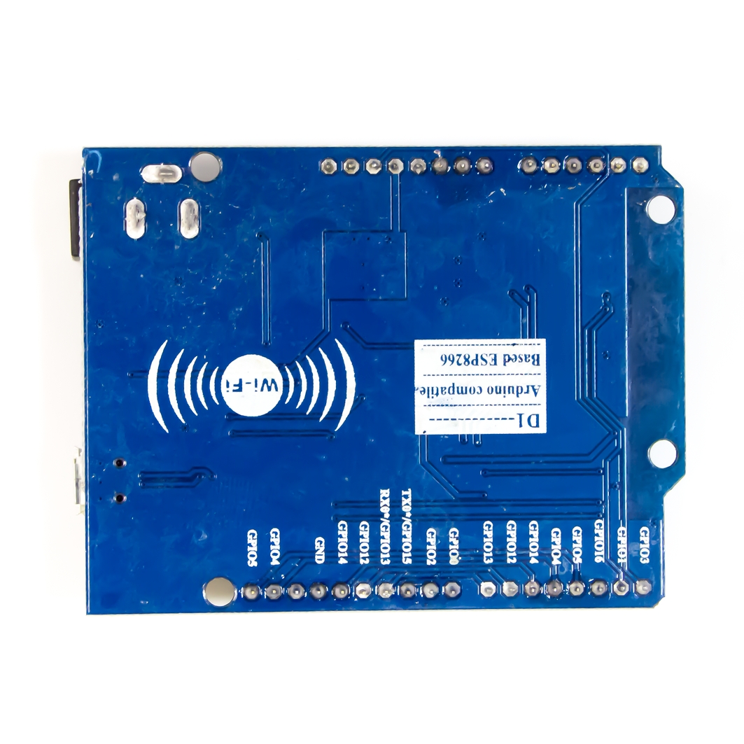
Контроллер с Wi-Fi WeMos D1 на ESP8266
![]()
в корзину >
Обсудить вопросы приобретения, не технические!
*Доступно общение только текстовыми сообщениями, звонки и аудио сообщения не обслуживаются
С этим товаром берут
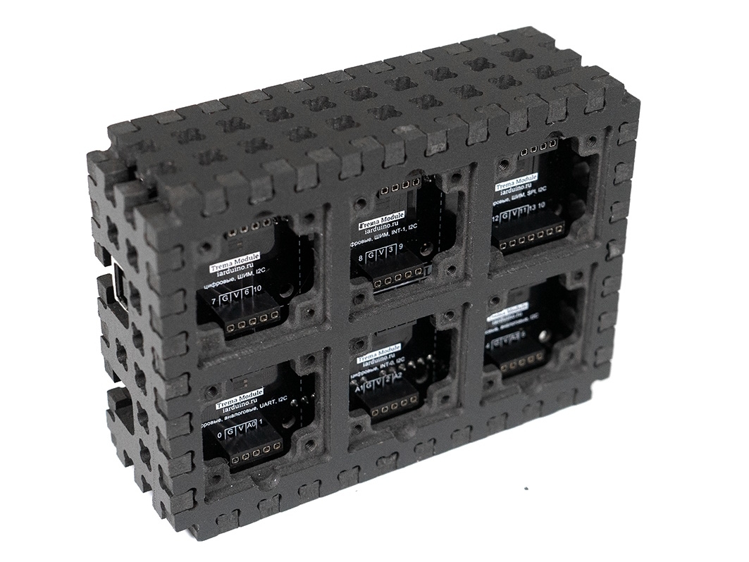
Конструктор ПВХ Чёрный «Корпус Set Box»
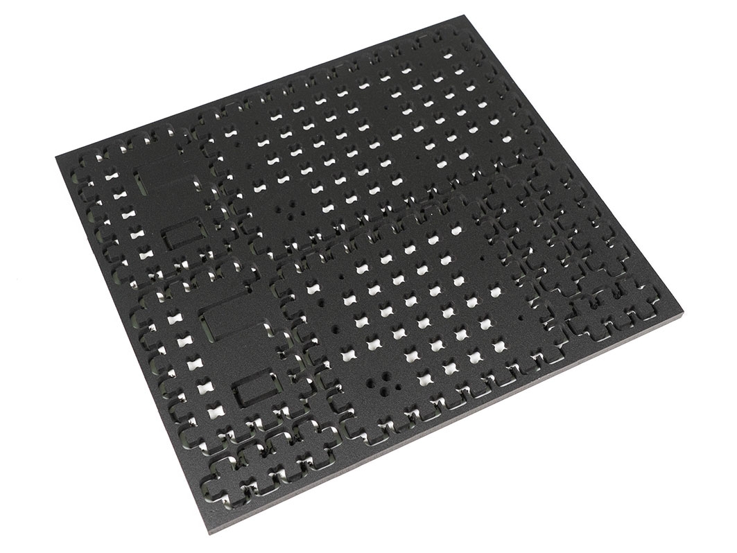
Конструктор ПВХ Чёрный «Крепления Arduino»
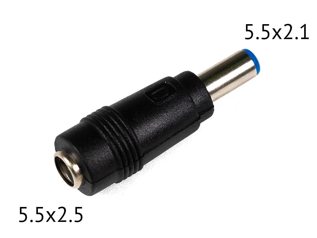
Переходник 5.5×2.5 на 5.5×2.1
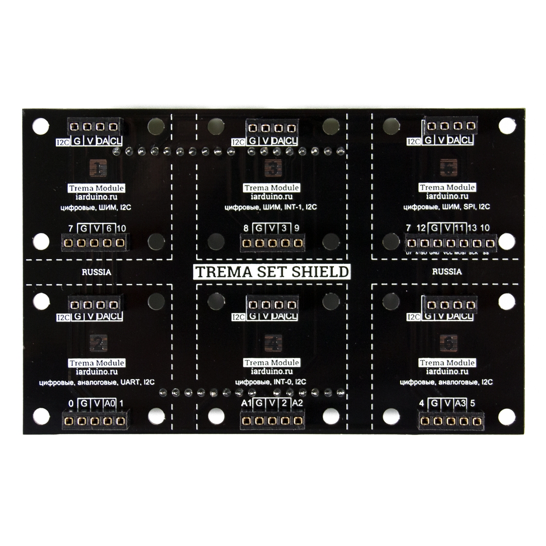
Trema Set Shield
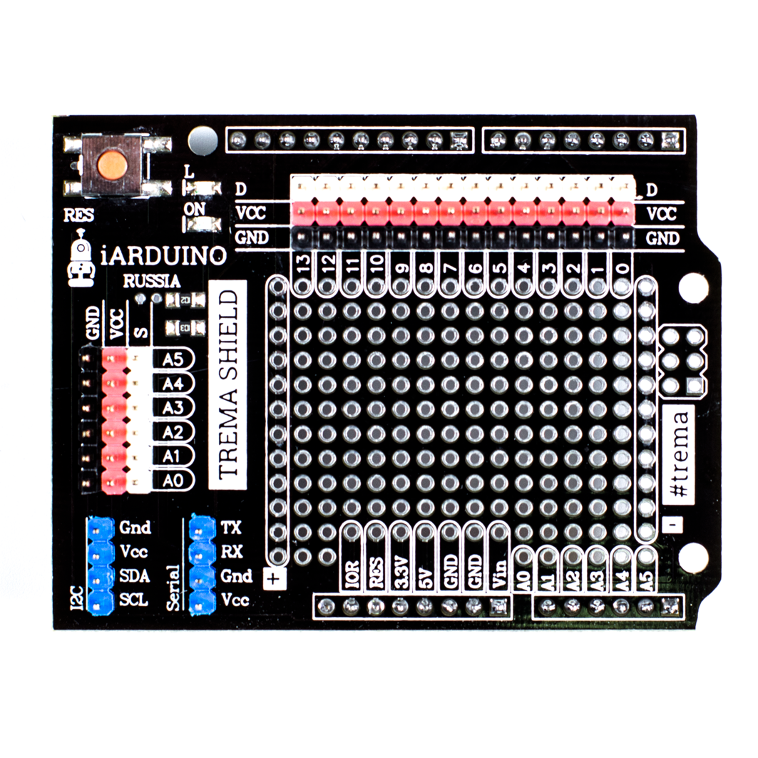
Trema Shield
Общие сведения
Контроллер WeMos D1 R2 Wi-Fi — это плата, позволяющая управлять различными модулями вместо Arduino, но в отличии от большинства плат Arduino, у платы WeMos D1 mini больший объем памяти программ и памяти ОЗУ, она построена на базе 32 разрядного микроконтроллера с большей тактовой частотой и оснащена встроенным WiFi модулем, который можно настроить как клиент (STA), точка доступа (AP), или клиент+точка доступа (STA+AP).
Характеристики
- Ядро: ESP-8266EX, 80/160 МГц;
- Объём Flash-памяти: 4 Мб;
- Питание: 9-24 В
- Количество цифровых выводов: 11 (10 поддерживают interrupt/pwm/I2C/one-wire);
- Количество аналоговых выводов: 1 (максимальное входное напряжение 3,2 В);
- Разъём: Micro USB
- Поддержка Arduino / NodeMcu;
- Программирование через Serial или OTA (беспроводная загрузка программного кода по Wi-Fi);
- Наличие WI-FI модуля;
Программное обеспечение
Для работы с платой вам необходимо установить драйвер для чипа СH340G.
Скачать (загрузить) программу Arduino IDE для создания, редактирования и загрузки скетчей в Arduino или Genuino, Вы можете с официального сайта.
С подробной инструкцией по загрузке, установке и настройке программы Arduino IDE можно ознакомиться в разделе Wiki — Установка/настройка программной оболочки Arduino IDE для Window
Комплектация
Установка драйвера
Если при подключении контроллера в Arduino IDE не появляется новый COM-порт, возможно не был установлен драйвер USB-UART преобразователя. Инструкции по ручной установке драйвера:
Ссылки
Убедитесь, что у вас есть все необходимое для вашего проекта – ниже представлен выбор необходимых дополнительных услуг!