Собираем Wi-Fi робота
Давно мечтал сделать Wi-Fi робота, которым можно было бы управлять удаленно. И вот наконец настал тот день когда я смог управлять роботом через интернет, видеть и слышать все что происходит вокруг него.
Заинтересовавшихся приглашаю под кат
Для создания робота использовались следующие комплектующие:
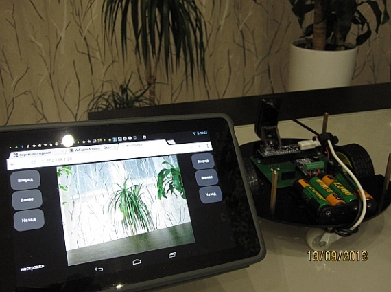
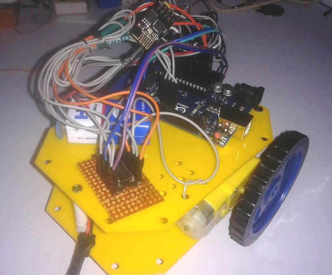
Вот так выглядит собранный мной робот, без верхней крышки.

Теперь все по порядку:

Расположение компонентов на материнской плате. Я установил только Arduino Nano, драйвер двигателей и звуковой излучатель HC:

Роутер wr703N прикрепил к нижней части платформы робота на двухсторонний скотч:

Веб камера прикреплена на мебельный уголок, к штатным отверстиям платформы, предусмотренных для сервомоторов:

СyberWrt — это прошивка собранная на базе OpenWrt и предназначенная в первую очередь для роботов, умного дома и других устройств построенных на базе популярных моделей роутеров Tp-Link mr3020 b Wr703N. У СyberWrt максимально возможный объем свободного места для инсталляции пакетов — 1.25Мб. По умолчанию установлен веб сервер и все операции можно проводить через встроенный веб интерфейс. Сразу после перепрошивки, роутер доступен в сети по кабелю и по WiFi, как точка доступа. Через веб-интерфейс можно работать в режиме «командной строки» — через веб терминал и в файловом менеджере, в котором можно редактировать, загружать, удалять, создавать, копировать файлы и многое другое.
После прошивки роутера, он доступен как WiFi точка доступа с именем «CyberBot», подключаемся к нему заходим на главную страницу роутера. Вот так выглядит веб интерфейс сразу после прошивки.
Устанавливаем модули Драйвер FTDI, Драйвер video и CyberBot-2.
Прошиваем контроллер ардуино.
Код программы робота получился достаточно простым, но его достаточно для того что бы удаленно управлять роботом через локальную сеть или интернет.
Код адаптирован под контроллеры Arduino с ATmega168/328 на борту и использует библиотеку CyberLib.
Эта библиотека помогает из контроллера выжать максимум его возможностей и уменьшить объем конечного кода
В коде используется WDT, для того что бы робот не смог зависнуть.
Так же код поддерживает управление камерой по осям X и Y, но у меня не было свободных сервомоторов и я не смог воспользоваться этой функцией:
#include #include Servo myservo1; Servo myservo2; long previousMillis; http://cyber-place.ru/attachment.php?attachmentid=600&d=1389429469 uint8_t LedStep = 0; // Счетчик int i; boolean light_stat; uint8_t inByte; uint8_t speed=255; //максимальная скорость по умолчанию #define init void setup() < myservo1.attach(9); // Подключение сервоприводов к порту myservo2.attach(10); // Подключение сервоприводов к порту init; // Инициализация портов D11_Low; // Динамик OFF randomSeed(A6_Read); //Получить случайное значение horn(); //звуковое оповещение готовности робота UART_Init(57600);// Инициализация порта для связи с роутером wdt_enable (WDTO_500MS); >void loop() < unsigned long currentMillis = millis(); if (LedStep == 0 && currentMillis - previousMillis >500) < // Задержка 0,5 сек. previousMillis = currentMillis; LedStep = 1; >if (LedStep == 1 && currentMillis - previousMillis > 500) < // Задержка 0,5 сек. previousMillis = currentMillis; LedStep = 2; >if (LedStep == 2 && currentMillis - previousMillis > 500) < // Задержка 0,5 сек. LedStep = 0; >if (UART_ReadByte(inByte)) //Если что то пришло < switch (inByte) // Смотрим какая команда пришла < case 'x': // Остановка робота robot_stop(); break; case 'W': // Движение вперед robot_go(); break; case 'D': // Поворотjт влево robot_rotation_left(); break; case 'A': // Поворот вправо robot_rotation_right(); break; case 'S': // Движение назад robot_back(); break; case 'U': // Камера поднимается вверх myservo1.write(i -= 20); break; case 'J': // Камера опускается вниз myservo1.write(i += 20); break; case 'H': // Камера поворачивается вправо myservo2.write(i += 20); break; case 'K': // Камера поворачивается влево myservo2.write(i -= 20); break; case 'B': // Бластер D12_High; break; case 'C': // Клаксон horn(); break; case 'V': // Включить/Выключить фары if(light_stat) < D8_Low; light_stat=false; >else < D8_High; light_stat=true; >break; > if(inByte>47 && inByte <58) speed=(inByte-47)*25+5; //принимаем команду и преобразуем в скорость >wdt_reset(); > void horn() < for(uint8_t i=0; ivoid robot_go() < D4_Low; analogWrite(5, speed); analogWrite(6, speed); D7_Low; >void robot_back() < D4_High; analogWrite(5, 255-speed); analogWrite(6, 255-speed); D7_High; >void robot_stop() < D4_Low; analogWrite(5, 0); analogWrite(6, 0); D7_Low; >void robot_rotation_left() < D4_Low; analogWrite(5, speed); analogWrite(6, 255-speed); D7_High; >void robot_rotation_right()
Все собрано и прошито, теперь включаем робота и управляем им удаленно.
На PC кроме экранных кнопок можно управлять еще с клавиатуры, клавишами W, A, D, S, X
В дальнейшем планирую научить робота ориентироваться в пространстве и рисовать карту помещения.
WiFi Controlled Robot using Arduino
There are many types of Robots, from the simple ones like a Toy car to the advanced ones like industrial Robots. We have already covered many types of Robots using different technologies, have a look at them:
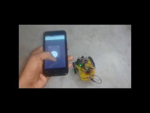
And now we are adding one more Robot in our ‘Robotics Projects’ section, this time we are going to make a Wi-Fi controlled Robot using Arduino and Blynk App. This Arduino based Robot can be controlled wirelessly using any Wi-Fi enabled Android smart phone.
For demonstration of Wi-Fi Controlled Robot, we have used an Android Mobile App named “Blynk”. Blynk is a very compatible app with Arduino, to make IoT based project. This App can be downloaded from the Google Play Store, and can be easily configured.
Steps for configuring Blynk App:
1. First download it from Google Play Store and install it in Android mobile phone.
2. After this, it is required to create an account. You may use your current Gmail account.
3. Now select Arduino Board and give a name for your project.
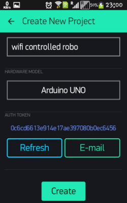
4. Note down the Auth Token Code or simply mail it to your Email Account and then copy and paste in Arduino sketch (Program Code).
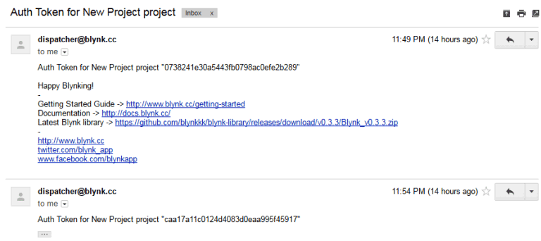
5. Enter this Auth Token Code in Arduino sketch.
// You should get Auth Token in the Blynk App. // Go to the Project Settings (nut icon). char auth[] = "caa17a11c0124d4083d0eaa995f45917";
6. Then click on create button in Blynk app.
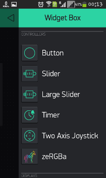
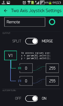
7. Now Select the Joystick Widget, Click on Joystick, Configure the Joystick (see the Video at the end) and hit the back button.
8. After it press Play button at the right top of screen.
All this process, of using the Blynk App, has been clearly explained in Video, given in the end.
Required Components:
- Arduino UNO
- ESP8266 Wi-Fi Module
- USB Cable
- Connecting wires
- L293D
- DC Motors
- Batteries
- 10K POT (optional)
- Robot chassis plus wheel
- Roller caster
- Android Mobile phone
- Blynk App
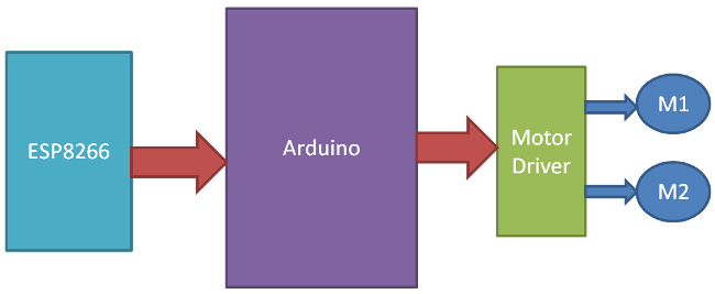
Circuit Explanation:
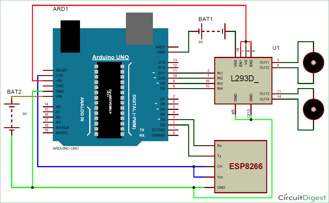
Circuit Diagram of Wi-Fi controlled robot is given below. We mainly need a Arduino and ESP8266 Wi-Fi module. ESP8266’s Vcc and GND pins are directly connected to 3.3V and GND of Arduino and CH_PD is also connected with 3.3V. Tx and Rx pins of ESP8266 are directly connected to pin 2 and 3 of Arduino. Software Serial Library is used to allow serial communication on pin 2 and 3 of Arduino. We have already covered the Interfacing of ESP8266 Wi-Fi module to Arduino in detail.
A L293D Motor Driver IC is used for driving DC motors. Input pins of motor driver IC is directly connected to pin 8, 9, 10 and 11 of Arduino. And DC motors are connected at its output pins. Here we have used 9 Volt battery for driving the Circuit and DC motors.
Working Explanation:
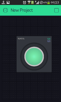
Working of the Wi-Fi controlled Robot is very easy, we just need to Drag or Slide the Joystick in the direction, where we want to move the Robot. Like if we want to move the Robot in Forward direction then we need to Drag the Joystick ‘circle’ in Forward direction. Likewise we can move the Robot in Left, Right and Backward direction by Dragging the joystick in respective direction. Now as soon as we release the Joystick, it will come back to centre and Robot stops.
Blynk App sends values from Two Axis Joystick to Arduino, through Wi-Fi medium. Arduino receive the values, compare them with predefined values and move the Robot accordingly in that direction.
Programming Explanation:
Program is almost readymade available in Arduino IDE. We just need to download Blynk Library for Arduino. And after making some modifications, user can make own Wi-Fi controlled robot.
First we have included all the needed libraries to run this code in Arduino IDE, and then entered Auth Token, from the Blynk app, in the auth string. Here we are connecting Wi-Fi serial pin with Software Serial of Arduino. Selected pin 2 as RX and 3 as TX.
#define BLYNK_PRINT Serial // Comment this out to disable prints and save space #include #include // Set ESP8266 Serial object #include SoftwareSerial EspSerial(2, 3); // RX, TX ESP8266 wifi(EspSerial); // You should get Auth Token in the Blynk App. // Go to the Project Settings (nut icon). char auth[] = "caa17a11c0124d4083d0eaa995f45917";
Then we defined output pins(8,9,10,11) for motors and wrote some direction functions to move the Robot in particular direction: void forward(), void backward(),void right() and void left()
After this, in setup function we initialise all the required devices, like giving direction to motor pins, begin serial communication, providing Wi-Fi username and password.
Now we have checked some conditions for controlling the robot. Here we have selected virtual pin 1 (V1) for taking input from Blynk App to control the robot. As we have used marge option in app so we will get x and y axis values at same pin.
BLYNK_WRITE(V1) < int x = param[0].asInt(); int y = param[1].asInt(); if(y>220) forward(); else if(y<35) backward(); else if(x>220) right(); else if(x
At last we need to run blynk function in loop, to run the system.
#define BLYNK_PRINT Serial // Comment this out to disable prints and save space
#include
#include
// Set ESP8266 Serial object
#include
SoftwareSerial EspSerial(2, 3); // RX, TX
// You should get Auth Token in the Blynk App.
// Go to the Project Settings (nut icon).
char auth[] = «caa17a11c0124d4083d0eaa995f45917»;
#define m11 8
#define m12 9
#define m21 10
#define m22 11
void forward()
digitalWrite(m11, HIGH);
digitalWrite(m12,LOW);
digitalWrite(m21,HIGH);
digitalWrite(m22,LOW);
>
void backward()
digitalWrite(m11, LOW);
digitalWrite(m12,HIGH);
digitalWrite(m21,LOW);
digitalWrite(m22,HIGH);
>
void right()
digitalWrite(m11, HIGH);
digitalWrite(m12,LOW);
digitalWrite(m21,LOW);
digitalWrite(m22,LOW);
>
void left()
digitalWrite(m11, LOW);
digitalWrite(m12,LOW);
digitalWrite(m21,HIGH);
digitalWrite(m22,LOW);
>
void Stop()
digitalWrite(m11, LOW);
digitalWrite(m12,LOW);
digitalWrite(m21,LOW);
digitalWrite(m22,LOW);
>
void setup()
// Set console baud rate
Serial.begin(9600);
delay(10);
// Set ESP8266 baud rate
// 9600 is recommended for Software Serial
EspSerial.begin(9600);
delay(10);
Blynk.begin(auth, wifi, «username», «password»); // wifi username and password
pinMode(m11, OUTPUT);
pinMode(m12, OUTPUT);
pinMode(m21, OUTPUT);
pinMode(m22, OUTPUT);
>
BLYNK_WRITE(V1)
int x = param[0].asInt();
int y = param[1].asInt();
// Do something with x and y
/* Serial.print(«X ; Y field field—name-field-video field—type-text-long field—label-above»>