- Как у меня заработал WIFI для Arduino ESP8266 ESP-12E
- Платы, которые использовались при написании статьи:
- Материалы со страницы «Инструкция 1».
- Почему бы не использовать совмещенную плату UNO+ESP8266?
- UPD
- Arduino ESP8266 ‘Shiald’, step by step
- Requirements
- Flashing Firmware
- Using Arduino as USB-Serial Converter for the ‘Shiald’
- Flashing
Как у меня заработал WIFI для Arduino ESP8266 ESP-12E
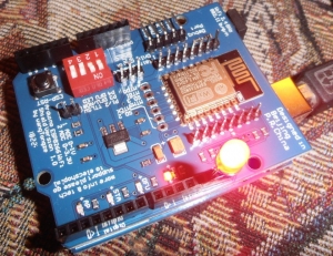
Плата ESP8266 ESP-12 ESP-12E UART Wi-Fi устанавливается сверху на плату Arduino UNO R3 и позволяет получать доступ к управлению и состоянием Arduino из интернет. И я заставил этот слоеный пирог заработать.
Компоненты Arduino для работы покупал в магазине All Electronics Trading Company.
Все быстро пришло. Почти все из того что заказал в этом магазине было отличного качества.
Исключение составляла комбинированная плата с разными датчиками, светодиодами и кнопками s.click.aliexpress.com/e/ct9JuGza. Эта плата была какой-то ручной пайки, но полностью работала.
Платы, которые использовались при написании статьи:
Закачал пустой скетч в Arduino U3.
void setup () <
// поместите здесь свой установочный код, чтобы запустить его один раз:
>
void loop () // поместите ваш основной код здесь для повторного запуска:
>
Действуя по инструкции 1 я ничего не достиг. Все комбинации перепробовал.
Раньше где-то слышал, что процедура прошивки требует намного большей мощности, чем штатная работа, и мощности питания от Arduino не всегда хватает.
На момент прошивки нужен отдельный источник питания. Заподозрил что у меня именно эта ситуация.
Esp8266 питается от 3.3V, а Uno использует 5V. В инструкции 1 написано, что 5V не трогаем. Автор инструкции 2 подключает на свой страх и риск (о чем говорит) плату Esp8266 к 5V выходу UNO R3. Я тоже так решил сделать, подключив все вот так.
Тут дело сдвинулось с мертвой точки, почти сразу же опять застопорившись.
Плата синхронизировалась, но как-то не до конца.
Содержимое окна FLASH_DOWNLOAD_TOOLS_v2.4_150924 было почти такое же, как в инструкции 1:
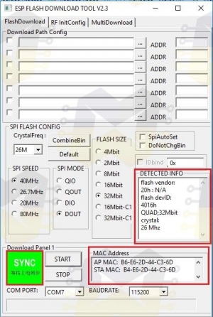
но у меня поле MAC adress заполнилось, а вот DETECTED IINFO оставалось пустым.
В логе содержалась фраза «error read crystal«. Подумал было что все-таки сжег плату, подав напряжение 5V на свой страх и риск.
Но нашел подобную проблему в ветке форума ERROR FLASHING FIRMWARE. Проблему решили, записав в Arduino U3 пустой скетч.
Да я же делал это в самом начале!
Снова записал пустой скетч и на этом этапе все заработало. А именно — содержимое окна FLASH_DOWNLOAD_TOOLS_v2.4_150924 стало таким же, как в инструкции 1.
И прошивка залилась в плату ESP8266 ESP-12 ESP-12E UART Wi-Fi.
Может, когда на первом этапе ничего не получалось, что-то залил в Arduino R3?
Начал дальше следовать инструкции 1, поместив плату ESP8266 на Arduino UNO R3 — и опять ничего не ладилось. Что бы не делал с переключателями Р1, Р2 — не проходили команды.
Снова обратился к инструкции 2.
Вернул подключение ESP8266 к UNO через Debug Port, но уже с использованием 3.3V — flash загрузчик уже не надо было использовать и решил не испытывать плату на прочность.
И отправил при таком подключении команду «AT+UART_DEF=9600,8,1,0,0». Вернуло ERROR.
Тут оказалось, что внимательно надо следить за регистрами и за отсутствием пробелов. Команды копировал с сайтов, а там были пробелы и поэтому возвращало ERROR.
Также нужно следить за регистрами. Команда «AT» принимается как в верхнем, так и в нижнем регистре. Остальные команды только в верхнем.
Дальше действовал по инструкции 1.
Небольшой трудностью на этом этапе было привязать статичный IP адрес — пришлось выяснять пароль от модема ZyXel Keenetic 4G II.
Теперь можно было с Web-страницы при помощи кнопки управлять светодиодом, подключенным к Arduino UNO R3, и видеть его состояние.
Материалы со страницы «Инструкция 1».
На данный момент на странице инструкции 1 www.instructables.com/id/ESP8266-ESP-12E-UART-Wireless-WIFI-Shield-TTL-Conv/ такие версии используемых файлов:

Почему бы не использовать совмещенную плату UNO+ESP8266?
Есть в природе плата, аналогичная вроде-бы двум описываемым выше.
UNO + WiFi R3 ATmega328P + ESP8266 (32 Мб памяти), USB-TTL CH340G. Совместимость Uno, NodeMCU, WeMos ESP8266.
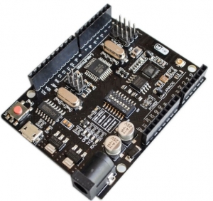
Получается дешевле на 100р, чем описываемые выше в паре.
UPD
С ней оказалось все немного по другому.
Arduino ESP8266 ‘Shiald’, step by step
A little while ago I ordered a couple of Arduino Uno cards along with a couple of ESP8266 WiFi shields. It being my first hands-on with Arduinos, I was rather naive in my choice of shields. I got mine from banggood.com when they were listed as “ESP8266 ESP-12E UART WIFI Wireless Shield TTL Converter For Arduino UNO R3 Mega“, but while figuring out how to use them I found that various other budget tech vendors sell them. Their identifying feature is a charming little typo printed on the PCB :
Arduino ESP8266 WiFi Shiald Version 1.0 by WangTongze

The major problem is that the only official documentation is in Chinese (Mandarin?), something I haven’t a clue about. But by trawling the web and with a lot of trial and error I was eventually able to get code running on the card. I’ve written the process up spread across previous posts here, but it is rather convoluted, so for future ref. I’m pulling it together here. If you haven’t already bought one of these shields, you may well be better off getting something like a Wemos card.
Requirements
- Arduino ESP8266 WiFi Shiald Version 1.0 by WangTongze
- Computer with Arduino IDE loaded (I’m using a regular laptop with Ubuntu OS)
- USB-TTL level serial converter – NB. I didn’t have one of these, but it turns out to be straightforward to use an Arduino Uno as a pass-through converter
- USB cable, jumper leads (4 with a socket on one end)
Flashing Firmware
I must admit I don’t know if this step is entirely necessary, there may well be a quicker approach. But it worked for me, and is useful for resetting the card.
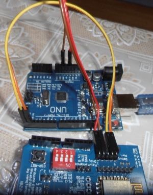
Using Arduino as USB-Serial Converter for the ‘Shiald’
Shiald Debug TX => Uno Pin 1 (TX) Shiald Debug RX => Uno Pin 0 (RX) Shiald Debug 5V => Uno 5V Shiald Debug GND => Uno GND Uno Reset => Uno GND (Uno USB => Computer USB)
Flashing
Before connecting the Arduino to the computer, set the DIP switches on the Shiald as follows:
I had to tweak my paths a little bit, I forget the details, but whatever it took to get esptool.py running from the shell.
The script needed tweaking for the appropriate paths. Run:
– and the appropriate port should be obvious on the resulting list. My version of the script looks like this:
#!/bin/sh # ESPToolDir="$HOME/Downloads/esptool" FirmwareDir="$HOME/Arduino/ESP8266_NONOS_SDK" cd "$FirmwareDir" port=/dev/ttyACM0 if [ ! -c $port ]; then port=/dev/ttyACM1 fi if [ ! -c $port ]; then echo "No device appears to be plugged in. Stopping." fi printf "Writing AT firmware in 3. " sleep 1; printf "2. " sleep 1; printf "1. " sleep 1; echo "done." echo "Erasing the flash first" "esptool.py" --port $port erase_flash "esptool.py" --chip esp8266 --port $port \ write_flash -fm dio -ff 20m -fs detect \ 0x0000 "$FirmwareDir/bin/boot_v1.7.bin" \ 0x01000 "$FirmwareDir/bin/at/512+512/user1.1024.new.2.bin" \ 0x3fc000 "$FirmwareDir/bin/esp_init_data_default_v08.bin" \ 0x7e000 "$FirmwareDir/bin/blank.bin" \ 0x3fe000 "$FirmwareDir/bin/blank.bin" echo "Done."
The messages given by esptool.py are pleasingly informative, but I found I have to press the reset button on the Shiald when the message got to:
. Hard resetting. esptool.py v2.2.1 Connecting.
The original script suggested using miniterm to check this had worked. I used the Arduino IDE. First unplug the USB and set the DIP switchesto all Off.
After plugging back in again & launching the IDE, go to Tools -> Port and choose whatever looks right. Under Tools -> Board choose NodeMCU 1.0 (ESP 12E module). Then go to Tools -> Serial Monitor.
In the serial monitor, set the baud rate to 112500 and then click reset on the Shiald.
You should get a message that ends in ‘ok‘.
At this point you should be able to communicate with the Shiald using AT commands. Two useful things:
This will flip the baud rate down to 9600.
Gives the versions of various things.
At this point it should be possible to upload software to the Shiald (with the DIP switches Off, Off, On, On) from the Arduino IDE.
Tools -> Board NodeMCU 1.0 (ESP12)
I’ve found that it often takes several attempts (and hits of the reset switch) to get a successful upload, no matter what the baud rate.
e.g. this minimal web server:
#include #include #include const char* ssid = «AllPay Danny»; const char* password = «not this»; ESP8266WebServer server(80); // HTTP server on port 80 IPAddress ip(192, 168, 0, 14); // where xx is the desired IP Address IPAddress gateway(192, 168, 0, 1); // set gateway to match your network IPAddress subnet(255, 255, 255, 0); // set subnet mask to match your network void setup() < Serial.begin(9600); WiFi.disconnect(); // Disconnect AP WiFi.config(ip, gateway, subnet); WiFi.mode(WIFI_STA); WiFi.begin(ssid, password); // Connect to WIFI network // Wait for connection while (WiFi.status() != WL_CONNECTED) < delay(500); Serial.println("."); >Serial.print(«Connected to «); Serial.println(ssid); Serial.print(«IP address: «); Serial.println(WiFi.localIP()); server.on(«/», []()< server.send(200, "text/plain", "Hello World"); >); server.begin(); // Start HTTP server Serial.println(«HTTP server started.»); > void loop()
Pointing a browser at the chosen IP address should now work.
There’s a complication to comms between the Arduino and the Shiald. It seems the serial Tx/Rx lines of the ESP8266 connect to ports 1 & 2 on the Shiald – the Arduino’s Tx/Rx.
Again, I’m not really sure how essential this is, but it certainly works to wire other ports on the Arduino to the serial on the Shiald and use the SoftwareSerial lib. For reliability a baud rate of 9600 seems advisible.
Here’s a little example that worked for me:
#include SoftwareSerial mySerial(2, 3); // RX, TX on Arduino void setup() < Serial.begin(9600); mySerial.begin(9600); >void loop() < if (mySerial.available()) < String msg = mySerial.readString(); Serial.print("Data received: "); Serial.println(msg); >> Remember before uploading to remove the jumpers and change the board settings in the Arduino IDE.
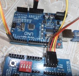
At runtime, the following wiring worked for me:
Arduino | Shiald GND - Debug GND +5v - Debug 5v Digital 2 - Digital 0 Digital 3 - Digital 1
For my own application I want to be able to read values from the Analog Ins of the Arduino (6) and ESP8266 (1) and expose these (and one or two other little things) on a web server over Wifi. I’ve made a bit more progress towards this, will upload code to this project’s GitHub repo once I’ve tweaked to hide passwords.
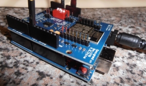
So…this is my current setup:

The lower part is a Shiald piggybacking an Arduino Uno, the upper another Arduino acting as a serial interface direct to the Shiald. Each Arduino is going to a USB port on the laptop.
The wiring – the Shiald has its pins 1 & 2 bent out of line and connected instead via jumpers to pins 2 & 3 on the host Arduino. The Arduino acting as a serial interface has is as above, less the power lines.
For writing code to the Shiald, the DIP switches are at Off, Off, On, On. At runtime they’re at On, On, Off, Off.
I’m still using the Arduino IDE, flipping between USB port and board (Arduino Uno/NodeMCU 1.0).
It’s a bit of a pain flipping between the configs, but takes less time than uploading a reasonably long program to the Shiald, so I can’t really complain.