- Wifi gpio raspberry pi
- Table of Contents
- Specifications and Features:-
- Raspberry Pi Pico Pinout
- Components Required
- Circuit Diagram :
- MicroPython Script for Interfacing ESP8266 Wi-Fi Module
- Raspberry Pi Pico-ESP-01-ESP8266- Web Server
- Interfacing of ESP8266 WiFi Module with Raspberry Pi Pico
- Result:
- ESP-12F Raspberry Pi GPIO SDIO Wifi
Wifi gpio raspberry pi
The ESP-01 ESP8266 is a serial WIFI Wireless Transceiver Module developed based on ESP8266 SoC with integrated TCP/IP protocol stack that can give any microcontroller access to your WiFi network. This Wi-Fi Module is capable of of either hosting an application or offloading all Wi-Fi networking functions from another application processor.
The ESP-01 ESP8266 module has a powerful onboard processing and storage capabilities that allow it to be integrated with the sensors and other application specific devices through its GPIOs . Below are the specifications for this ESP8266 Wi-Fi Module.
Please note The ESP8266 Module is not capable of 5-3V logic shifting and will require an external Logic Level Converter. Please do not power it directly from your 5V dev board.
Table of Contents
Specifications and Features:-
- 802.11 b/g/n
- Wi-Fi Direct (P2P), soft-AP
- Integrated TCP/IP protocol stack
- Integrated TR switch, balun, LNA, power amplifier and matching network
- Integrated PLLs, regulators, DCXO and power management units
- +19.5dBm output power in 802.11b mode
- Power down leakage current of
- 1MB Flash Memory
- Dimensions: 25 x 15 x 11 mm (LxWxH)
- PCB Thickness: 1mm
- Weight: 2 gm
- Integrated low power 32-bit CPU could be used as application processor
- SDIO 1.1 / 2.0, SPI, UART
- STBC, 1×1 MIMO, 2×1 MIMO
- A-MPDU & A-MSDU aggregation & 0.4ms guard interval
- Wake up and transmit packets in < 2ms
- Standby power consumption of < 1.0mW (DTIM3)
We have seen previously the interfacing guides for this Wi-Fi Module with Arduino and PIC Microcontroller. In this Tutorial we will Interface this ESP8266 Wi-Fi Module with Raspberry Pi Pico development board to set up Wi-Fi wireless connectivity. This Wireless Wi-Fi Connectivity with Pico development board help to facilitate all the IOT prospective features so we can host the data and Post the data to the server and any API connected over clouds like we can send Sensors reading to the Webserver, Sending Data over Email.
Before proceeding further you may look at our previous tutorials for Interfacing ESP-01 ESP8266 Wi-Fi module.
Recommended Tutorials:
To proceed further with concept of Interfacing the ESP-01 Wi-Fi Module with Raspberry Pi Pico Board we need to
- Download and install the latest version of Python3 on Windows PC
- Download and install the latest version of either uPyCraft IDE or Thonny IDE.
- Setting up an MicroPython within Raspberry Pi Pico.
Refer below tutorials to follow above steps to make our Pico board ready for programming
As the ESP-01 Wi-Fi module communicating over serial bus , the interfacing or connection with Raspberry Pi Pico Development board will be very easy as we need to used only two UART0 GPIO pins of Pico board. We will connect Wi-Fi module at TX(0) pin/ GPIO0 and RX(0) pin/ GPIO1. Refer below Pinout and circuit diagram for your better interfacing.
Raspberry Pi Pico Pinout
The following image is the pinout diagram of Raspberry Pi Pico Board , it is 40 pin development board that includes 26-GPIO, GND, Debug and +5VCC pins. Raspberry Pi Pico GPIOs are the multifunction pins which can be configured or used for the one the function at a time. Like Digital or Analog configuration.

Components Required
To do this project we need very few components as listed below
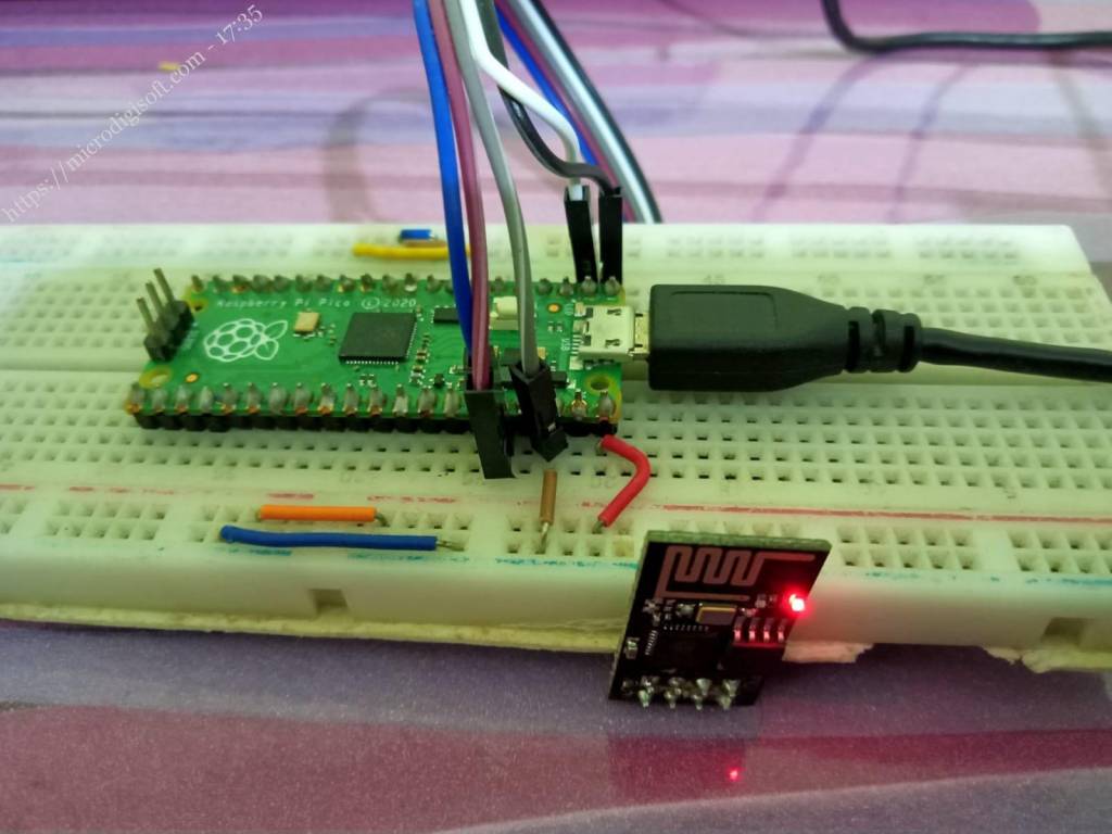
Circuit Diagram :
Below is the Circuit diagram for interfacing ESP-01 Wi-Fi Module Module with Pico Board using MicroPython programming.

MicroPython Script for Interfacing ESP8266 Wi-Fi Module
To know how to program Raspberry Pi Pico board using MicroPython tools please refer below tutorials step by steps:
To establish a communication between ESP8266 module and Raspberry Pi Pico we need to sends AT commands to the ESP8266 module to configure ESP8266 as a TCP web server. In the below MicroPython script we have passed AT commands serially one by one enable Wi-Fi module so it can communicate with Pico Board and setup a Webserver. To program Raspberry Pi Pico board we will use uPyCraft IDE , copy the below code and save it as a PIco-ESP8266.py.
PIco-ESP8266.py
import uos import machine import utime recv_buf="" # receive buffer global variable print() print("Machine: \t" + uos.uname()[4]) print("MicroPython: \t" + uos.uname()[3]) uart0 = machine.UART(0, baudrate=115200) print(uart0) def Rx_ESP_Data(): recv=bytes() while uart0.any()>0: recv+=uart0.read(1) res=recv.decode('utf-8') return res def Connect_WiFi(cmd, uart=uart0, timeout=3000): print("CMD: " + cmd) uart.write(cmd) utime.sleep(7.0) Wait_ESP_Rsp(uart, timeout) print() def Send_AT_Cmd(cmd, uart=uart0, timeout=3000): print("CMD: " + cmd) uart.write(cmd) Wait_ESP_Rsp(uart, timeout) print() def Wait_ESP_Rsp(uart=uart0, timeout=3000): prvMills = utime.ticks_ms() resp = b"" while (utime.ticks_ms()-prvMills)'+'\r\n') uart0.write(''+'\r\n') uart0.write('Raspberry Pi Pico-ESP-01-ESP8266- Web Server
Interfacing of ESP8266 WiFi Module with Raspberry Pi Pico

After Downloading the PIco-ESP8266.py to the Pico board we need to AT commands starts executing sequentially to configure the ESP-01 board as webserver. The response each AT commands will get printed on the Python shell window.
Ready to download this file,please wait! . download ok exec(open('PIco-ESP8266.py').read(),globals()) Machine: Raspberry Pi Pico with RP2040 MicroPython: v1.16 on 2021-06-18 (GNU 10.2.0 MinSizeRel) UART(0, baudrate=115200, bits=8, parity=None, stop=1, tx=0, rx=1, txbuf=256, rxbuf=256, timeout=0, timeout_char=1, invert=None) CMD: AT resp: AT OK CMD: AT+GMR resp: AT+GMR resp: AT+CIPSERVER=0 OK 1,CLOSED CMD: AT+RST resp: b'AT+RST\r\r\n\r\nOum 0x2a\r\nload 0x3ffe8000, len 2124, room 8 \r\ntail 4\r\nchksum 0x07\r\nload 0x3ffe8850, len 9276, room 4 \r\ntail 8\r\nch8\x80\x0c\x8es\x88\x03\x8c\xe3No\x83d\x8e\x98l\x130\xec\x0c\x88\x80l\x8es\x88\x03s\x88\x03\x87\t\x907\xff\r\nready\r\nWIFI CONNECTED\r\n' CMD: AT+RESTORE resp: b'AT+RESTORE\r\r\n\rhksum 0x2a\r\nload 0x3ffe8000, len 2124, room 8 \r\ntail 4\r\nchksum 0x07\r\nload 0x3ffe8850, len 9276, room 4 \r\ntail 8\r\nchksum 0xba\r\ncsum 0xba\r\n\x8c\xe3No\x83l\x8e\x84l\x130\xec\x0c\x88\x80\x0c\x8es\x88\x03\x8c\xe3No\x83l\x8e\x8fl\x1b0\xec\x0c\x88\x80\x04\x8es\x88\x03\x84\xe3Ng\x83l\x8e\x90l\x130\xec\x04\x88\x80l\x8es\x88\x03s\x88\x03\x8f\t\x907\x03F\xe7\x93N\xe3c\x0c\x88\x83\x84cs\xf1cv\x03c\xc1\x13N\xe0Io\xe0Io\xc1cNl\x01cx\x7f\x93o\xf0\x13o\xce\x93N\x8c\x03F\x00\x03F\x8f\to\xfc\x01cpy\x0c\x88\x8c\x04\x8e\x83\x8c\x8f\x80l\x8e\xe3\x8c\x8f\x8c\xec\x8e\xecl\x8f\xc8d`\t\x03O\x98\x1b\x03F\xe7\x93N\xe3c\x04\x88\xe3\xec\x8f\xc6\x0cc@\x03O\xe0\x03F\xef\x93N\xe3c\x0c\x88\x83\x0c\x8e|l\x8es\x88\x03s\x88\x03\r\nready\r\n' CMD: AT+CWMODE? resp: AT+CWMODE? +CWMODE:2 OK CMD: AT+CWMODE=1 resp: AT+CWMODE=1 OK CMD: AT+CWMODE? resp: AT+CWMODE? +CWMODE:1 OK CMD: AT+CWJAP="JioFiberhome3G","Micro@123" resp: AT+CWJAP="JioFiberhome3G","Micro@123" WIFI CONNECTED WIFI GOT IP OK CMD: AT+CIFSR resp: AT+CIFSR +CIFSR:STAIP,"192.168.29.83" +CIFSR:STAMAC,"8c:aa:b5:c4:e6:da" OK CMD: AT+CIPMUX=1 resp: AT+CIPMUX=1 OK CMD: AT+CIPSERVER=1,80 resp: AT+CIPSERVER=1,80 OK Starting connection to ESP8266. resp: 0,CONNECT 1,CONNECT +IPD,0,454:GET / HTTP/1.1 Host: 192.168.29.83 Connection: keep-Kit/537.36 (KHTML, like Gecko) Chrome/102. connectionId:0 ! Incoming connection - sending webpage CMD: AT+CIPCLOSE=0 resp: 0,CLOSED10.0; Win64; *,*/*;q=0.8 Referer: http://192.168.29.83/ Accept-Encoding: gzip, deflate Accept-Language: en-US,en;q=0.9 Waiting For connection. Result:
In the result of AT command response in Python shell window we can find the IP address configured and connected with ESP8266 module. Enter the same IP address in your web browser to get the Webserver response from Pico board using ESP-01 module. It indicated that our Interfacing of Wi-Fi module on successfully completed and it is ready to send any data like sensor reading over webserver.
ESP-12F Raspberry Pi GPIO SDIO Wifi
Get fast Wifi via the Raspberry Pi GPIO header using the SDIO bus of the ESP8266. Also with audio jack for the zero.
For ESP8266
Populate R1, R2, R3, R4, R5 and R6. DON’T populate R7 or R14. Populate R13 to use GPIO6 for CH_EN. R8 is an optional 10K pullup for RST, as only using the internal pullup can lead to stability issues. For Power, C1 0.1uf and C8 10uf should always be populated. If using the RPi’s 3V3 supply put a wire / jumper across the two pin header at the bottom. If using a regulator populate the SOT223 (e.g. with AMS1117 or LD1117S33) and populate C6 10uf and C7 0.1uf. For Audio
The audio uses GPIO12 and GPIO13 to which you need to remap PWM0/PWM1 (see below).
You probably want to use components with good tolerances here unless you don’t care about audio quality. Although it might not matter as not much care was taken with the routing, its just an easy ‘add on’. Populate R9,R10 with 270R. C2,C3 with 33nf. R11, R12 with 150R. C4, C5 with 10uf. Then populate the PJ313D audio jack.
The two BAV99 SOT23 dual diodes are protection for the RPi’s GPIO and are optional but very strongly recommended as its a few cheap diodes vs a potentially dead Pi.
dtoverlay=sdio,poll_once=off #make sure everything is up to date sudo apt-get update && sudo apt-get -y upgrade #install tools sudo apt-get -y install bc rpi-update git libncurses5-dev
cd ~ sudo wget https://raw.githubusercontent.com/notro/rpi-source/master/rpi-source -O /usr/bin/rpi-source && sudo chmod +x /usr/bin/rpi-source && /usr/bin/rpi-source -q --tag-update rpi-source --skip-gcc
If this bug isn’t fixed https://github.com/notro/rpi-source/issues/17 then modify ./linux/Makefile and remove the line that reads EXTRAVERSION = + (line 4). Then create a new file in the ./linux directory called .scmversion with just a + character in it. Clone and install the ESP8089 driver.
cd ~ git clone https://github.com/al177/esp8089.git cd esp8089 make sudo make install
Rebooting When you reboot the pi without removing power you may need to reset the esp8266. You can do this using the GPIO pin that you wired up to CH_EN (probably GPIO6)
echo 6 > /sys/class/gpio/export echo low > /sys/class/gpio/gpio6/direction echo high > /sys/class/gpio/gpio6/direction
If you need to reload the module without rebooting the pi, unload the driver first or it gets very upset.
dtoverlay=pwm-2chan,pin=12,pin2=13,func=4,func2=4
wget http://www.freespecialeffects.co.uk/soundfx/sirens/police_s.wav sudo aplay police_s.wav
mmc1: new high speed SDIO card at address 0001
Thats confirmation that your module is at least being read. If you’re not getting an interface after this is probably because the driver is not being loaded. You can also try the below to check the ESP8266 is identifying as you’d expect.
sudo cat /sys/kernel/debug/mmc1/ios clock: 50000000 Hz actual clock: 41666666 Hz vdd: 21 (3.3 ~ 3.4 V) bus mode: 2 (push-pull) chip select: 0 (don't care) power mode: 2 (on) bus width: 0 (1 bits) timing spec: 2 (sd high-speed) signal voltage: 0 (3.30 V)
pi@raspberrypi:~ $ cat /sys/bus/sdio/devices/mmc1\:0001\:1/modalias sdio:c00v6666d1111
1 bit mode You shouldn’t need to use 1 bit mode, 4 bit mode should just work without removing the flash. So you can skip this step. I’ve left it here in-case you really want to use it this way. If you want /HOLD asserted on the flash populate R7 (you may want to put a value there, e.g. 200R). Don’t populate R3 or R4.
If using 1 bit mode you can re use GPIO27 as the enable pin for the
ESP8266 so populate R14. Otherwise populate R13 and use GPIO6. If you’re going to use the 1 bit mode you’ll need the latest sdio device tree overlay. (this PR https://github.com/raspberrypi/linux/pull/1255).
sudo rpi-update sudo reboot Should bring it to you if you don’t have it. The easiest way to check is to read /boot/overlays/README and check if the sdio section has the bus_width parameter. 1 bit mode users must include the bus width parameter in their sdio overlay params.
dtoverlay=sdio,poll_once=off,bus_width=1 1 Bit-mode users also need to clear the QE bit in the SPI flash’s register. Otherwise the flash will ignore the HOLD pin. I have a simple python script here to enable you to do that. Just download and run it. Ideally put the ESP8266 to sleep first (e.g. GPIO27 or GPIO6 low).
echo 6 > /sys/class/gpio/export echo low > /sys/class/gpio/gpio6/direction
wget https://raw.githubusercontent.com/jacksonliam/rpi-bitbang-spiflash/master/progflash.py sudo python progflash.py