What is wifi header
As you may noticed from other technology that I posted, the way I study about a communication technology is always same. Study and understand the details of frame structure and then understand how these frames are exchanged at each step of communication process (protocol).
Overview of WLAN Frame
Followings are some of the bullelts for WLAN Frame. (The list would get longer as I learn more)
- WLAN doesn’t use 802.3 Ethernet frames
- There three different types of WLAN frame named Control, Management and Data frame.
- Max Frame size is 2346 bytes and they are typically fragmented at 1516 bytes.
- Preamble is always sent at 1 Mbps
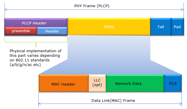
This is the frame being exchanged between the mobile device and Access point. The overall frame is structed as shown below.
The ‘Network Data’ shown in Green is the part which are eventually eventually conveyed to wired backbone and all the other portion (PHY, DataLink, Packet Trailer) are used for communicating between the mobile client and access point. PHY and ‘Data Link’ part will be main subject of WLAN frame.
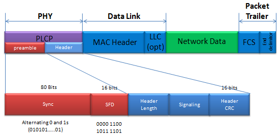
Now let’s look into the details of PLCP. PLCP is a kind of header deing added at PHY layer. It consists of two main parts, preamble and Header as shown below.
The first part of PLCP is for ‘Sync’ (Synchronization). This is a part made of 80 bits of alternation 0 and 1s.
The next portion is SFD (Start Frame Delimiter). This is a kind of tag indicating the start of physical frame and it is a specifically determined 16 bit sequence (0000110010111101).
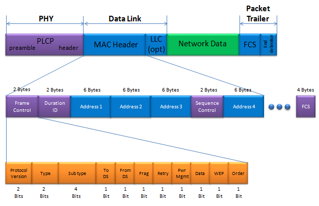
MAC Header would be a most complicated structure of the frame. The most important information contained in the MAC header would be as follows.
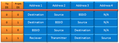
You see four different locations allocated for Address. What kind of address is assigned to which address field is determined by ‘To DS’ and ‘From DS’ field. The mapping between DS field and Address field are specified as follows.
Regardless of the contents in the frame, the structure of MAC header is same. Then how do we (the WLAN device) knows what kind of the information (data) is contained in the frame. ‘Type’ and ‘Sub Type’ field determines the characteristics of the frame.
Type field (2 bits) determines the major characteristics of the contents carried by the frame and ‘Sub type’ defines the details of the information.
The ‘Type’/’Sub Type’ and characteristics of the contents are mapped as shown in the following table. This table is mostly for 802.11 a,b,g and there is some changes (additions) in recent specification (e.g, 802.11ac, 802.11ad). Regarding the changes in recent specification, I would not list in this table and I will list those changes in separate pages dealing with 802.11ac or 802.11ad.
Initial element of 802.11 header
Although not all data transmitted over a network is in «network byte order», fields in Internet protocol standards like IPv4, IPv6, TCP, and UDP are in «network byte order» which follows big-endian byte order. However, some protocols that are transmitted over TCP or UDP, and even those over which IP is transmitted, may use little-endian byte order. To print the data as 0x4288 on both big-endian and little-endian machines, you will have to convert it from little-endian byte order to host byte order.
Is there an ethertype field in 802.11 header
When a higher layer protocol is being transported by 802.11, the Type/Subtype field of its header will be either «Data» (0x20) or «Qos Data» (0x28). Typically, a SNAP header (rfc1042) will follow the 802.11 header, which will indicate the type of payload being conveyed, such as IP, ARP, and so on.
In theory, it has the capability to support a variety of layer 2 protocols and utilize any LLC header.
Wifi — Is there an ethertype field in 802.11 header, If 802.11 is carrying any higher layer protocol, it’s 802.11 header Type/Subtype field will be «Data» (0x20) or «Qos Data» (0x28), and there will usually be a SNAP header (rfc1042) above the 802.11 header which will convey the type of payload (IP, ARP etc.) It is of course in theory able to carry any layer 2 protocol, …
DevOps & SysAdmins: Is there an ethernet header in
DevOps & SysAdmins: Is there an ethernet header in IEEE 802.11Helpful? Please support me on Patreon: https://www.patreon.com/roelvandepaarWith thanks & prai
C pcap 802.11 header
According to section 7.1.1 named «Conventions» in IEEE Std 802.11-2007:
Fields in figures are numbered from 0 to k, with a field length of k + 1 bits. To obtain octet boundaries within a field, take the bit numbers of the field modulo 8. Numeric fields longer than a single octet are displayed in order of significance, from lowest to highest bit numbers. The PLCP receives octets in fields longer than a single octet in ascending order from the octet with the lowest numbered bits to the octet with the highest numbered bits.
The order in which octets longer than a single octet are sent to the PLCP is from the one with the lowest numbered bits to the one with the highest numbered bits, indicating that they are transmitted in little-endian order rather than big-endian order. This implies that a 16-bit field with the value 0x0080 will be transmitted as a byte with the value 0x80 followed by a byte with the value 0x00.
In the hex dump of Wiretap, the appearance of 80 00 actually represents 0x0080, as opposed to 0x8000.
It should be noted that the radiotap header’s length is not always 24 bytes, as it contains a length field that specifies the header’s actual length in little-endian format.
For the Association Request, the fc field’s first 8 bits are zero. However, assigning (packet+24) seems to skip the header. Can you please provide a hexdump of the initial 32 bytes of the packet?
Ieee 802.11 — Network Engineering Stack Exchange, While diving into the depths of wireless networks I have come across the different address fields in the MAC header of 802.11 network frames. A few thought experiments later I was confused about a certain point concerning wireless repeaters. Most wireless repeaters work as a wireless client and an access point …
Order of sending «Frame Control field»data of an 802.11 frame?
The IEEE standard 802.11, which is regrettably not presently accessible through the IEEE Get initiative, states:
In the MAC sublayer, the sequence of fields in the MPDUs or frames is presented in a specific order. Clause 7’s figures display the fields/subfields in the MAC frame and the order in which PLCP receives them. The fields/subfields are passed from left to right.
Each field in figures has its bits numbered from 0 to k, where k + 1 bits represent the length of the field. To obtain octet boundaries within a field, simply take the bit numbers modulo 8. Numeric fields that span multiple octets are arranged in ascending order of significance, from the lowest numbered bit to the highest numbered bit. Finally, the octets in multi-octet fields are transmitted to the PLCP in sequence, starting from the octet with the lowest numbered bits and ending with the octet containing the highest numbered bits.
The initial octet of the Frame Control field sent to the PLCP is the one containing B0, which includes the protocol version, type, and subtype fields. Following this, the next octet contains To DS, From DS, and More Frag. As a result, the first transmitted octet is the 00|01|0001 octet, which represents 10001000 in a byte in memory, with high-order bit to low-order bit, resulting in 0x88. The second transmitted octet is the 01000010 octet, resulting in 0x42.
The data is sent over the wire as 00010001 followed by 01000010 . In memory, it appears as 0x88 followed by 0x42. It is worth noting that the FC field, along with other multi-octet integral fields in 802.11, is transmitted in little-endian byte order, rather than big-endian byte order. Not all data transmitted over a network is in «network byte order,» as some protocols, including those transmitted over TCP or UDP, may use little-endian byte order. However, fields in Internet protocol standards such as IPv4, IPv6, TCP, and UDP are in «network byte order.
When processed as a 16-bit integral value on a little-endian machine, the value received would be 0x4288. In the case of a multiple-octet integral value on a little-endian machine, the first octet stored in memory is considered the low-order octet. Thus, your little-endian machine will display it as 0x4288. However, if the code were to run on a big-endian machine, it would display the value as 0x8842.
To print it correctly, the value should be shown as 0x4288 which is the little-endian format used for air transmission in 802.11. In Wireshark, the Frame Control field of the packet will be displayed as 0x4288 in the «packet details» pane, while in the «hex dump» pane it will be displayed as 88 42 due to the order in which the octets appear in memory.
In order to achieve consistency in printing 0x4288 on both big-endian and little-endian machines, it is necessary to convert it from little-endian byte order to host byte order. An effective solution for this is to utilize a macro such as pletohs() from Wireshark.
#define pletohs(p) ((unsigned short) \ ((unsigned short)*((const unsigned char *)(p)+1)<<8| \ (unsigned short)*((const unsigned char *)(p)+0)<<0)) To transmit the value in a manner that works regardless of the byte order of the machine, the most convenient approach would be to use a macro such as phtoles() from Wireshark.
#define phtoles(p, v) \ < \ (p)[0] = (unsigned char)((v) >> 0); \ (p)[1] = (unsigned char)((v) >> 8); \ > The issue at hand is a bug regarding byte ordering. It's important to note that performing (unsigned short int)(*(packet+2)) requires knowledge of whether your platform has the same byte order as the packet's contents. Since the byte order in your case differs from the packet's contents, the bytes end up swapping places, resulting in the problem you're experiencing.
Check out the Wikipedia page on byte order, also known as endianness, for further information.
The reason why FC is displayed as 4288 is because your system utilizes little-endian format for memory storage, whereas big-endian format is used for network communications.
Ensure with the following program
Your machine's endianness can be determined by the value printed. If the value printed is 0x78563412, it is little-endian. However, if it prints 0x12345678, then it is big-endian.
Below are some links that I believe will be useful.
1. The first link is to a webpage on sockets, which can be found at http://www.cs.odu.edu/~cs476/fall03/lectures/sockets.htm. 2. The second link is an example of htons in C, which is available at http://www.ccplusplus.com/2011/10/htons-example-in-c.html.
Is there an ethernet header in IEEE 802.11, 1 Answer Sorted by: 1 Ethernet is defined by IEEE 802.3, not IEEE 802.11 (Wi-Fi), so, no, there is no ethernet header in 802.11 frames; they are different network types, and IEEE 802.11 has its own frame format and headers. It the same with any of the IEEE 802.x LANs.
802.11 QoS data frames
At what point does a Logical Link Control (LLC) header accompany an IEEE 802.11 data frame?
While capturing on an 802.11 interface, it is recommended to have at least one packet present, even though it may seem strange for grouped packets. If monitoring without the monitor mode, the packet may appear with an Ethernet header at the start, but this is due to the adapter or driver converting the 802.11 header and LLC header into an Ethernet header.
However, Wireshark includes two bytes within the 802.11 header.
It is possible that the packet contains "Atheros padding" which is inserted by certain Atheros network adapters in monitor mode between the 802.11 header and the frame body. To confirm this, you can check if the "Data Pad" flag in the Flags field of the Radiotap header is set.
Is there an ethernet header in IEEE 802.11, While they have many similarities, there are also major differences. For one, 802.11 has up to four address fields that may or may not be used for different purposes depending on the type of frame, while 802.3 has two. In your example, the "IEEE 802.11" section should contain all your L2 information. So it …


